
|
| This
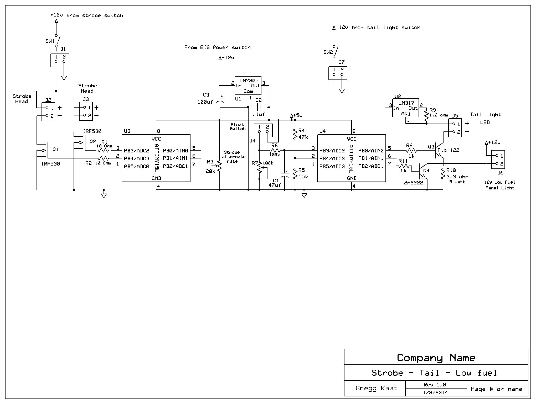
circuit combines a strobe,
Firefly tail light and low fuel warning in one package and does so in a
digital fashion. Attiny 85 microcontrollers are used and handle all the
thinking processes while a couple of FET's and another couple of
transistors handle all the higher current duties. The circuit is pretty
straight forward and shouldn't require much explanation. The
microcontrollers output pulses as necessary to trigger the transistor
switches on and off. The signal for the taillight soft on and soft off
in the same fashion as a firefly found in nature is accomplished with
pulse width modulation. An LM 317 is configured as a current limiter so
the led is not overdriven. Use a high power LED of your choice here.
The low fuel indication is monitored with a float switch in the fuel
tank. Refer to the analog low fuel circuit for that switch arrangement.
The pulses for the strobe leds are short ,so no current limiting
resistors are shown but you may want to add some depending on the leds
you end up using. The R3 pot will adjust the rate at which the strobe
will toggle from one wing to the other. The microcontrollers were
programed using my Arduino
UNO as an ISP. It took a couple of tries to get it to work but
ultimately did the job. Look on the net for tutorials on how to do
that. One microcontroller handles the strobe function while the other
handles the tail and low fuel. The sketches follow. Feel free to
edit if you have the skills but the code will function as is. Stobe Function /* Blink Turns on an LED on for 1/10th second, then off for 1/10th second twice and then alternates repeatedly. This example code is in the public domain. */ int potPin = A1; // analog pin used to connect the potentiometer int val = 0; // variable used to store the value from the analog pin // the setup routine runs once when you press reset: void setup() { // initialize the digital pin as an output. pinMode (3, OUTPUT); //output led 1 pinMode (4,OUTPUT); //output led 2 } // the loop routine runs over and over again forever: void loop() { val = analogRead(potPin); //set alternate rate equal to the value read from analog pin 0 // map the analog input range 0...1023 to a delay range 0 ... 3000 ms val = map (val,0,1023, 0, 3000); digitalWrite(3,LOW); // start led 1 off digitalWrite(4,HIGH); // turn strobe LED 2 on delay(80); // for .08 second digitalWrite(4, LOW); // turn led 2 off delay(80); // for .08 second digitalWrite(4, HIGH); // turn led 2 back on delay(80); // for .08 second digitalWrite(4, LOW); // turn led 2 off delay(val); // alternating delay determined by pot digitalWrite(3, HIGH); // turn strobe led 1 on delay(80); // for .08 second digitalWrite(3,LOW); // turn led 1 off delay(80); // for .08 second digitalWrite(3, HIGH); // turn led 1 back on delay(80); // for .08 second digitalWrite(3,LOW); // turn led 1 off delay(val); // alternating delay determined by pot and start over } Tail light and low fuel warning function #define anain1 A2 // use analog pin 2 as analog refernce input(Atinny85 pin 3) #define anain2 A3 // use analog pin 3 as analog sample input(Attiny85 pin 2) #define led1 2 // digital pin 2 is comparator output(Attiny85 pin 7) int led2 = 0; // digital pin 0 is fade output(Attiny85 pin 5) void setup() { pinMode(led1,OUTPUT); // make pin 2 an output } void loop() { int ain1 = analogRead(anain1); //pin 3 int ain2 = analogRead(anain2); //pin 2 // if analog input 1 is higher than analog input 2, set output if (ain1 > ain2) digitalWrite(led1,LOW); if (ain1 <= ain2) digitalWrite(led1,HIGH); // break in program - switch to fade // fade in from min to max in increments of 5 points: for(int fadeValue = 0 ; fadeValue <= 255; fadeValue +=5) { // sets the value (range from 0 to 255): analogWrite(led2, fadeValue); // wait for 20 milliseconds to see the dimming effect delay(20); } digitalWrite (led2, HIGH); delay (1000); // fade out from max to min in increments of 5 points: for(int fadeValue = 255 ; fadeValue >= 0; fadeValue -=10) { // sets the value (range from 0 to 255): analogWrite(led2, fadeValue); // wait for 20 milliseconds to see the dimming effect delay(20); digitalWrite (led2, LOW); } for(int x = 0; x < 5000; x++) { delay(1); } } Home Page |