|
|
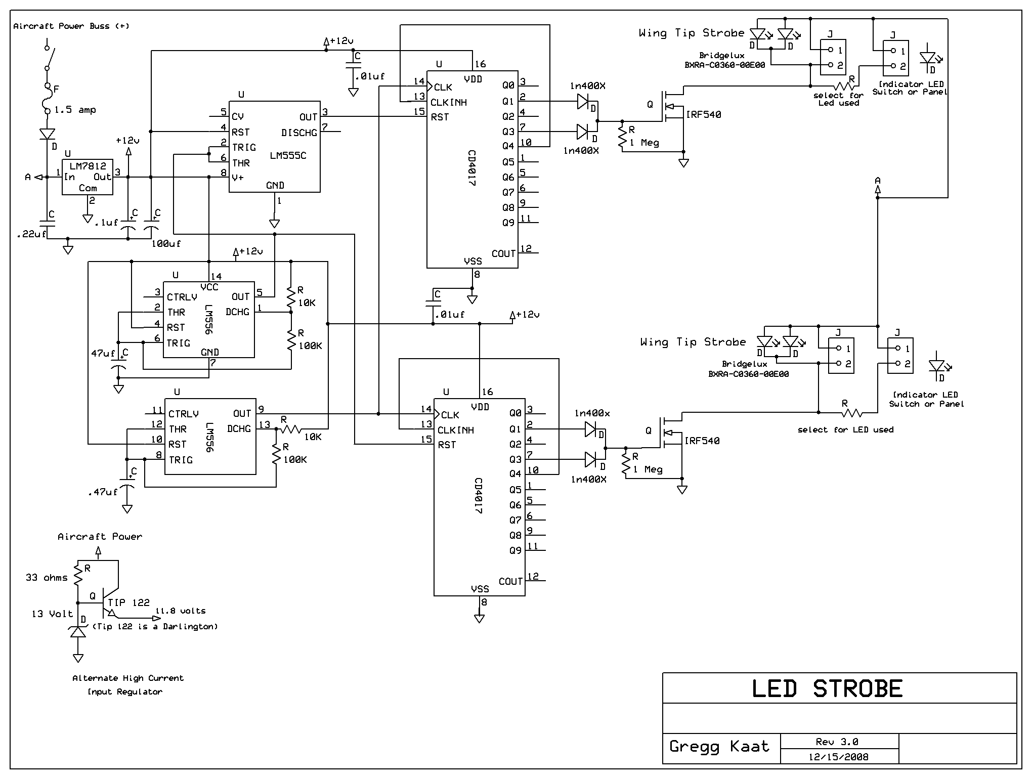
| One
of my first projects, this uses old school timers and counters. Most
IC's require some clean power so we have a 12 volt regulator from
aircraft power with a couple of caps as noise and ripple filters. .01
ufd capacitors are connected as close as possible to vdd on the 4017
chips to keep out noise and make them more stable. The
effect I wanted was a multi-flash strobe that toggled from side to
side. To accomplish this, two CD4017 decade counters are used 1ea
per side. Each IC requires a clock to function. The clock speed chosen
is the rate at which you want to flash your light. I used a 556 timer
to provide this clock as well as another clock to set the toggle rate
from one side to the other. The other 555 timer is hooked up as
inverter. Any inverter chip will do here. I happened to have a number
of 555's on hand. is all. When the reset on one 4017 is high, the other
will be low.One chip enabled, the other chip disabled. This provides
the toggle from side to side effect.
The diodes on the outputs are steering diodes. When the Q1 port goes
high, the diode is forward biased and a high appears on the gate of the
FET. At the same time, the steering diode on the Q3 port is reversed
biased and prevents the pulse from re-entering the ic. The FET is
configured as a switch. I like to use FET's because they handle a lot
of current and the high impedance input does not load the circuit. The
anode side of the strobe led is connected
to aircraft power. The cathode side is connected through the FET to
ground. When the FET is turned on, the ground is supplied to the strobe
and it will light. It only lights for the duration that the fet is
pulsed on. The pulses
are very short duration so I don't have any current limiting on the
stobe leds. This allows the current to come up very quickly. A high
power high current led should be used here. I use these.
When breadboarding this circuit, monitor the current on your strobe
line to make sure you don't over drive the leds. The optional panel
leds are redundent. I thought they might be distracting so I decided
not to use them. Pots could be used in the 556 oscillator circuits to
make the clock rates variable. I use a free program called 555 timer
pro to help model the circuits. Do a search on the net to find your
best download options for that. Per print, this circuit will give you a
dual flash per light and an approx toggle rate of 3 seconds. I'm doing
this from memory so the math may prove otherwise on the toggle
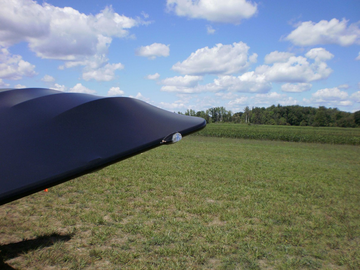
oscillator.) For my light fixtures, I found some inexpensive motorcycle marker lights that were small enough to fit on my wingtips. I took them apart and removed the existing lighting and substituted my own. When I built the plane, I ran wire through the wing spars before covering so that it would be available when I got ready to install this project. The final result can be seen Here. My final cost was in the neighborhood of 50 or 60 bucks. Far cheaper than the cost of aviation strobes and the added bonus that you can pat yourself on the back for doing it yourself. Home Page |