| Node | Receive DC Volts | Transmit DC Volts | Receive Vpp | Transmit Vpp |
|---|---|---|---|---|
| Q1 Base | 3.3 V | 3.2 V | 5.9 Vpp | 5.5 Vpp |
| Q1 Emitter | 3.5 V | 3.25 V | 4.9 Vpp | 4.5 Vpp |
| Q1 Collector | 8.7 V | 7.9 V | ||
| Q2 Base | 8.7 V | 0.0 V | 1.5 Vpp | 2.9 Vpp |
| Q2 Emitter | 8.65 V | 0.0 V | ||
| Q2 Collector | 8.7 V | 7.9 V | 1.5 Vpp | 15.8 Vpp |
| U1 pin 1 | 1.25 V | |||
| U1 pin 2 | 0.0 V | |||
| U1 pins 3,4 | 0.0 V | |||
| U1 pin 5 | 3.0 V | |||
| U1 pin 6 | 6.0 V | |||
| U1 pin 7 | 3.0 V | |||
| U1 pin 8 | 1.25 V | |||
| Antenna | 0.0 V | 11.0 Vpp (300mW) |
Note that the DC voltages on the bases and emitters of the transistors seem a little odd. This is due to the fact that the transistors are operating with large signals on them, and these signals look somewhat un-symmetrical. Normally one expects to see the base at 0.7V higher than the emitter for a transistor that is biased on. However, in the case of Q1, the distortions in the large waveform on base and emitter cause the average value of the voltage on each node to appear about the same.
One additional note about the pixie I have now: I finished this one after writing the article, and made another change in the design in the interest of a little more power: I used a 2N2222A for Q1 instead of a 2N3904. It seemed to have a little more gain at the higher collector current we're running at here (versus the original 40/80m Pixie)
Another change from the article: You might want to add
a 0.1 uF to ground from the collector of Q1. Especially if your battery
leads are very long. This could help prevent any instability problems
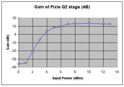
You can see that with less than about 4 dBm of drive, the stage has no gain at all! You really want 7 to 8 dBm from the oscillator stage to see full gain. At that point you'll probably get about 100 mW out. To get the 300mW or so the rig is capable of, you need about 10dBm of drive, which looks like about 1.6Vpp at the emitter of Q1, due to the non-linear nature of the load presented by Q2's base.
So, if the output from Q1 is too low, what could be the problem?
Here are some things to check: