|
|
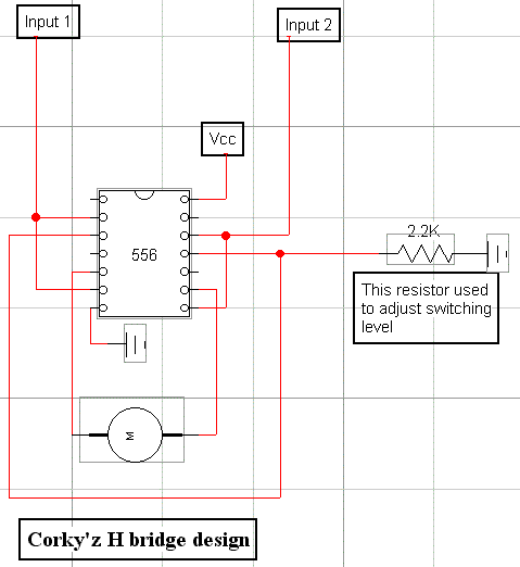
Here is Corky'z design for an H bridge which I thought was actually better than any of the others I had seen since it was comprised of only two components. On the breadboard this worked excellent although I did end up actually driving my motor through a '245 motor driver instead of the 556 outputs going directly to the motor. This design can source 200ma if I remember correctly. |
|
|
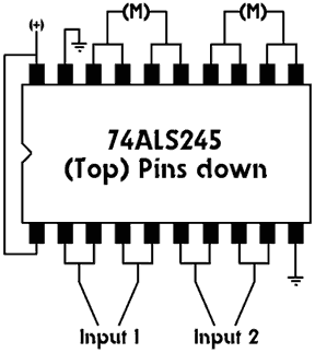
The '245 is an interesting little chip. When input is high it's output is high, when it's input is low it's output is low. This configuration drives two motors but you can combine the pins for more amperage and only drive one motor. Each pin set will source 100ma so all eight will drive 800ma. Not bad for a $1.29 chip. |
 |
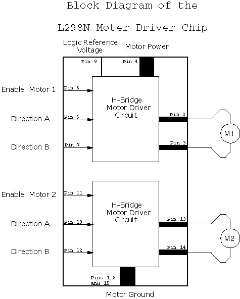
The L298N does the job of the two above circuits in one package. Sources up to 4 amps! Although at $5 a pop I only use it on finished bots. I really like the enable/disable pins on this chip, this can make pulse width modulation a snap no matter which way the motor(s) going. |
 |
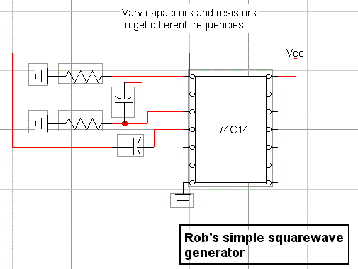
This is an OK (not great) square wave generator using the BEAM Microcore chip. Your square wave is coming out of pin 4. If you continue this configuration down the chip you can get up to 4 different waveforms at different frequencies. Twice as good as a 556 timer. Check beam-online for more information on this chip. |
 |
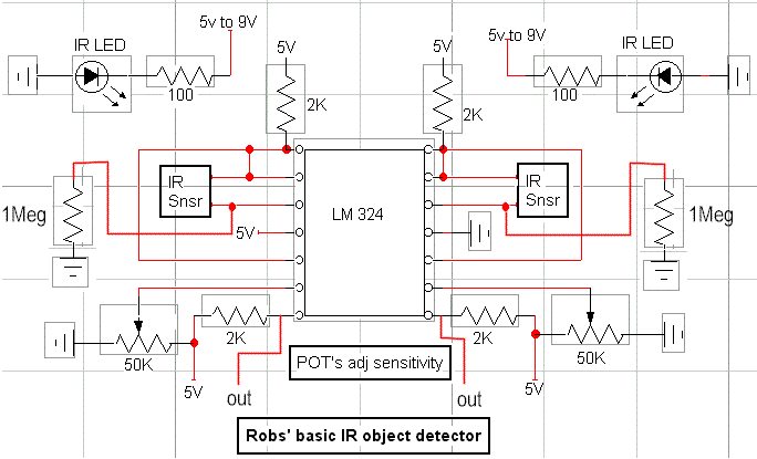
This is a non-modulated IR object detection circuit using the LM 324 Quad Op Amp. For each side I used one op amp to amplify the signal and then another to set a threshold (this provides adjustment). This way STAMP and PIC can easily work with the output that is 5v when on and almost zero when off. This circuit can be fooled when near very bright lights or open flames. |
 |
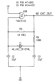
This circuit is a rock solid 40 KHz oscillator that works better than any other I've used. Very stable even at frequencies above 40 KHz. Put an IR LED on the output and you have yourself a very nice IR emitter. All kinds of usefulness here. This circuit from Reynolds Electronics. |
|
|
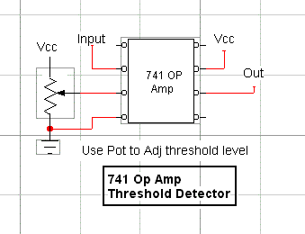
This is your basic comparator circuit using the 741 Op Amp. Nothing too fancy here. When input (pin 2) is higher than threshold (pin 3) output changes state, high to low. |
Some of these schematics I made, some I was given, others I don't know where I got them. If one is yours let me know and I'll give you credit and link to your site.