New RuF Bot pics at bottom!
 This particular robot is probably my favorite so far since it is really simple in all
respects. It is a ROV style robot that is controlled via joystick and serial RF link
running at 9600 baud. The best thing about this bot is that the electronics side of
the project is under $20. For those that have looked at the other bots here you will
notice this bot has evolved from the Stamp 1.0, once the drive train had been upgraded
from differential with tail wheel to differential track he no longer seemed to be the same
bot. So a new name and new control interface. This was my first project using
the PIC microcontroller and the TX/RX RF pairs from www.rentron.com
This particular robot is probably my favorite so far since it is really simple in all
respects. It is a ROV style robot that is controlled via joystick and serial RF link
running at 9600 baud. The best thing about this bot is that the electronics side of
the project is under $20. For those that have looked at the other bots here you will
notice this bot has evolved from the Stamp 1.0, once the drive train had been upgraded
from differential with tail wheel to differential track he no longer seemed to be the same
bot. So a new name and new control interface. This was my first project using
the PIC microcontroller and the TX/RX RF pairs from www.rentron.com
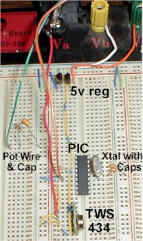
It seems like the most common question I get on this project is "What crystal did you use with your PIC?" The answer is it depends on what speed your Pic is.
A 20Mhz PIC will need a 20Mhz crystal, a 4Mhz PIC needs a 4 Mhz Crystal. Of course you could also forgo the crystal and caps and use a resonator but the crystal will be more precise for timing critical projects like this one.
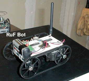
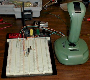
As you can see from the schematics and pictures he is very easily
constructed. Again, he is made from a 4 x 8 piece of plastic sheet and has modified
servos for motors. The servos are modified in a way that makes them DC gearhead
motors. The servos internal electronics have been completely removed and only the
motor and gears remain (hence the need for an H-Bridge).  The parts for the track setup came
from www.servolink.com
The parts for the track setup came
from www.servolink.com
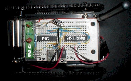
I found that the TX/RX pair and the serial communication built into
the PICBasic programming language for my PIC's worked very well together. I wasn't sure
how well the timing would work using Asynchronous Serial communication at 9600 baud, I
expected some problems at this higher speed but in testing found very little error. The
actual programming couldn't be easier since it is written in Basic and uses premade serial
communication routines. I simply read the position of the Potentiometer in the joystick
using the PICBasic 'POT' command and put the result in memory location 'B0'. From there
using the 'SEROUT' command I sent the contents of 'B0' to pin 6 of the TWS 434
transmitter. On the receiver end I use the 'SERIN' command and read the incoming data from
pin 3 on the RWS 434 and put the result in 'B0'. The value in 'B0' directly correlates to
joystick position, above 150 is right, below 106 is left, and in between is center. By
using these numbers I can define a deadzone.
At this point implications are easy to see. From the numbers
transmitted we can determine direction (left, right, etc) and also extent, or how far left
and how far right. With this information speed control can be introduced. The further the
number from 128 (center) the more speed is applied. In this example I used the pins on
PORTA of the PIC to control the motor direction and no speed control is used. Since our
serial data is 10 bits in length (1 start bit, 8 data bits, 1 stop bit) we can send 960
commands to the receiving PIC in one second. Not bad for under $20 in parts. Using
antennas made for 900Mhz cordless telephones I was able to get a range of 350 feet
outdoors, and when I boosted transmitter power slightly past 12 volts (not recommended) I
achieved a distance of 500 feet.
Note: I used the linear output on the reciever because I wanted to
see how much noise it would take to distort the signal before it became useless. To my
suprise the signal strength (at 500 feet) dropped off before any noise on the frequency
caused problems. Below is the source code written in PICBasic.
TX CODE:
symbol trisb = 134
symbol trisa = 133
symbol portb = 6
symbol porta = 5
low 1
input 0
input 2
start:
pot 0,50,B0
pot 2,50,B1
B0 = B0 * 5
B1 = B1 * 5
y:
if B0 <100 then yf
if B0 > 150 then yb
x:
if B1 <100 then xr
if B1 > 150 then xl
serout 1,n9600,(5)
goto start
yf:
serout 1,n9600,(2)
goto start
yb:
serout 1,n9600,(1)
goto start
xl:
serout 1,n9600,(3)
goto start
xr:
serout 1,n9600,(4)
goto start
end
RX CODE:
symbol trisb = 134
symbol trisa = 133
symbol portb = 6
symbol porta = 5
poke trisa, 0
poke porta, 0
low 0
input 1
prestart:
pause 400
poke porta, 10
pause 200
poke porta, 5
pause 200
poke porta, 6
pause 200
poke porta, 9
pause 200
poke porta, 0
pause 200
start:
serin 1,n9600,B0
if B0 = 1 then forward
if B0 = 2 then backward
if B0 = 3 then left
if B0 = 4 then right
if B0 = 5 then nomove
goto start
forward:
poke porta, 10
goto start
backward:
poke porta, 5
goto start
right:
poke porta, 6
goto start
left:
poke porta, 9
goto start
nomove:
poke porta, 0
goto start
end
Big thanks to Bruce for touching up my pics!!
New developements. Ruf bot has a new addition to the joystick controller and has
new interface software. The control joystick has a DB9 serial connector added to it
so it may be controlled using hyperterminal or the VB app I wrote when connected to an IBM
pc with a Windows OS. The joystick PIC basically shuts down when the DB9 connection
is made. The comm port specs are preset in the VB app except for port selection but
in hyperterminal they must be set in the initial connection screen. In this case
2400 baud, no parity, 8 data bits and one stop bit. The VB app can be downloaded here, and the screen shot is below.
The program still sends serial data (ASCII) just like the joystick
did but this time the Visual Basic app generates it. The serial data sent is the
string values of the numbers 8,5,2,4,6 which correspond to the arrows on the 10 key pad on
the right of most newer keyboards. This way using VB or hyperterminal the keys are
the same.
8=forward 5=stop 2=backward 4=left
6=right
For the updated program including Video Capture with control, download here.
A big thanks to Shrinkwrap software for keeping their code open source.
