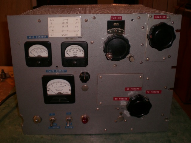
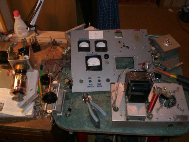
Front view of the 3-1000 Amp. Note that the front panel material is from another project. You can see the remains of a cutout of some sort on the left edge near the bottom. Also note that on the right side there are the rack mounting slots and none on the left side. The patch of metal behind the band switch is to cover a hole from the previous project. Over 50% of the screws seen on the front panel are there just to fill unused holes.

A closer look at part of the front panel. That ugly knurled knob sticking through an equally ugly hole is a locking device for the vacuum variable. The person adding the vacuum variable should have just taken it off the counter assembly as it was just held on with two screws. There is no need to lock the counter.
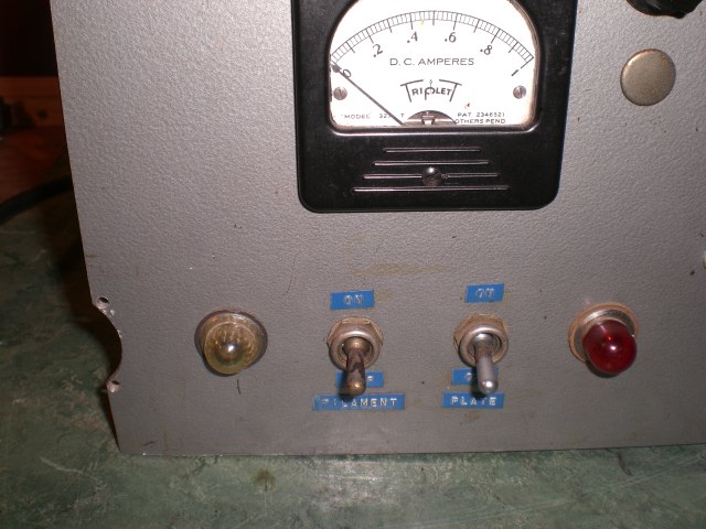
A closer look at the switches and pilot lights. Along with the part of a hole on the left edge of the panel. The pilot lights use neon lamps inside the holders. Note the plug filling yet another unused hole.
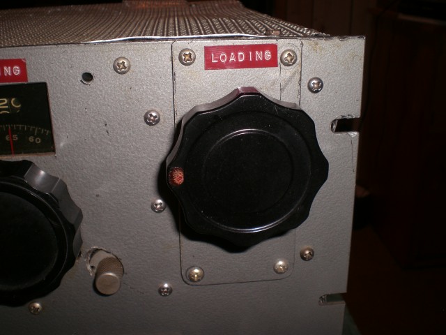
A close look at the loading control. The patch of metal is to cover many ugly holes only. You can also see the vacuum variable turns counter lock a bit better in this picture.
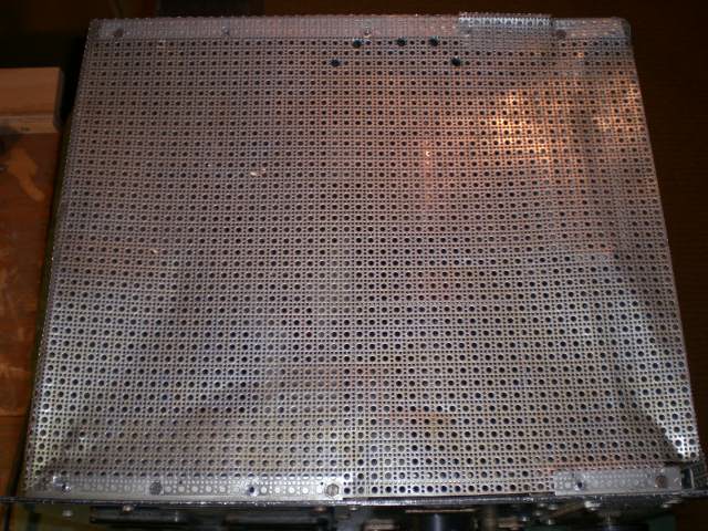
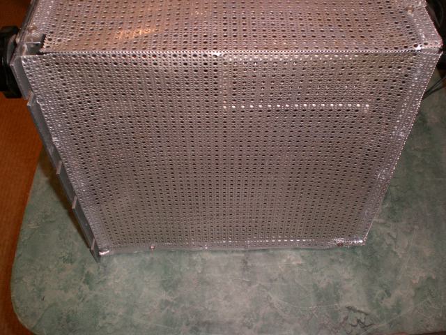
A look at the top. Has been banged up a bit. The holes in the back (top of the picture) are to allow access to the input tuning for adjustment.
This is the right side of the amp. You can see the loading capacitor somewhat through the metal covering.
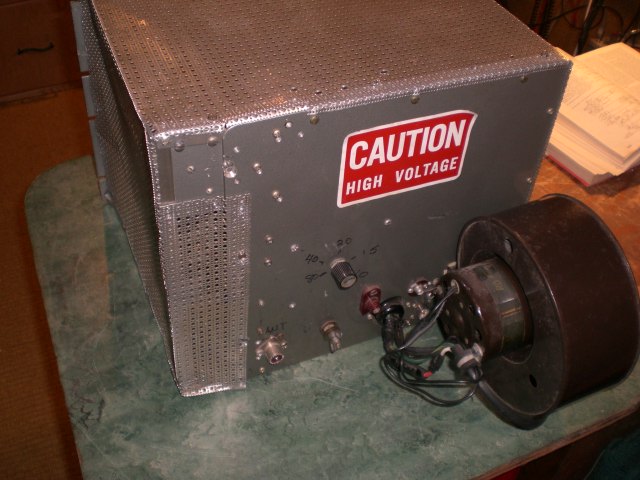
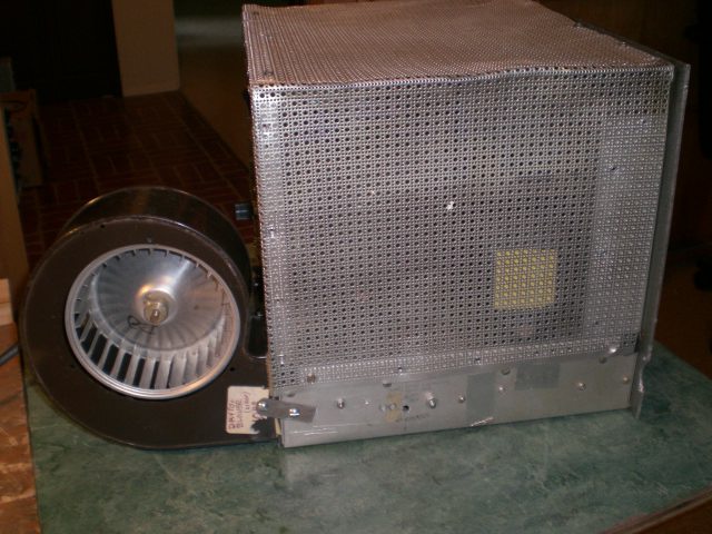
This is a view of the rear. A blower that looks like it came out of a small furnace. Unfortunately, the square opening of the blower was mated up to a ragged round hole in the chassis. The end result was a lot of air not making it into the chassis. The know on the back is the input band switching. The mechanism that linked it to the front band switch broke so the input coil box was turned around and stuck out the back. The reear panel is part of the original package. You can see where things were enlarged to accommodate the bigger tank circuit components on the left.
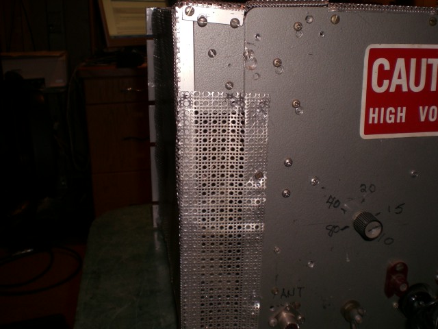
A closer look at the added area. The piece of metal at the top was to mount the loading capacitor. Then the covering metal just wrapped around and covered the addition.
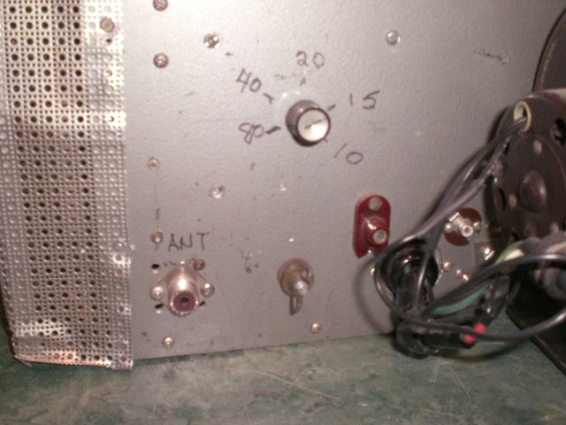
A closer look at the rear shoing the input band switch along with the output connector, the ground lug, the high voltage connector, and the PTT connector. The wiring is connected to a recessed 8-pin octal plug. It was wired in such a way that the fan ran as soon as you plugged in the power. No switch at all.
Left side of the amp. The pieces of tape on the chassis are to cover unused holes.
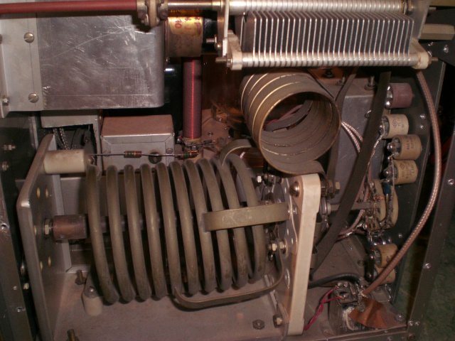
Right side of the amp showing the B&W 852 tank coil, the loading capacitor, and a switch with additional capacitors to switch in for additional loading. The bracket above the tank coil is part of the vacuum variable mounting.
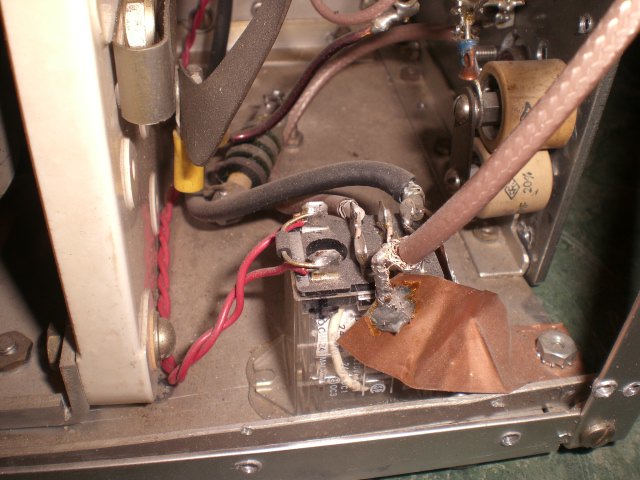
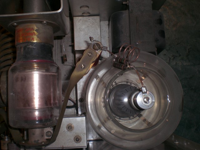
This is part of the antenna change-over. There is another relay under the chassis. I don't know why someone thought they had to add that piece of copper just to ground the braid of the coax.
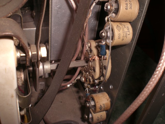
This is the switch coupled to the back of the band switch to add additional loading. The doorknob capacitors provide the additional loading. Right behind the B&W switch you can see an old dial string pully mounted on the shaft going to the switch on the rear of the amp. That pully was used to switch the input band switch which broke. Right idea but should have used a sprocket and chain type of setup.
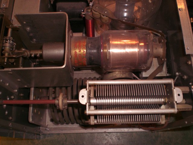
Top view showing the vacuum variable and the loading capacitor.
Anothe top view showing the tuning capacitor and the tube. You can see part of the input tuning box mounted on the back panel between the variable and the tube. Also to the front of the RF choke is a small box that housed the output RF detector.
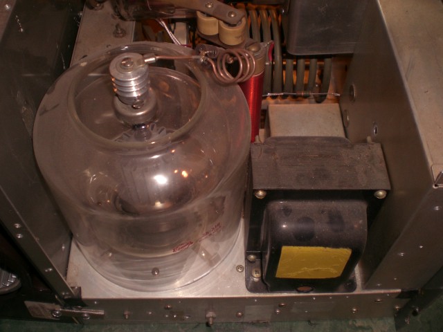
Another look from the left side showing the tube, the filament transformer, and the RF detector box. The metal to the front of the filament transformer is a shield covering the meters on the front panel.
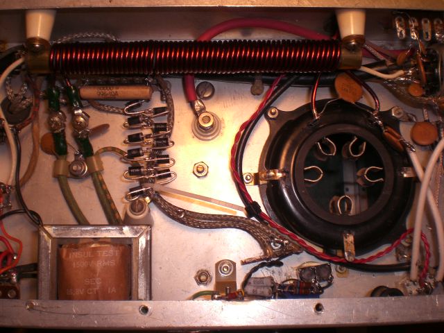
Bottom view of the chassis. The other part of the antenna switching is a very small white relay located in the bottom right of the chassis. All those diodes in series are used for the bias and the insulated standoff that they are connected to is not mounted to the chassis.
What a bunch of parts