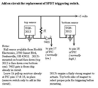
Below is a small circuit, which I have recently added to my kick pedal. This circuit provides more stable triggering by eliminating the mechanical contacts implemented in the original design.

For triggering of the hall sensors, a Radio Shack #64-1877 "high-energy ceramic magnet" is mounted under the aluminum foot pedal. Placement with reference to the sensors is somewhat critical. The magnet must come within close enough range to trigger both sensors (first the top, then the bottom). Additionally the magnet must return on release of the pedal, to an upper position which deactivates both sensors ( I actually had to remove a link from the chain of the pedal used, to accomplish this one).
There is approximately 1/16" between the sensors, with both mounted face down, top sensor above the bottom one (this allows the sensors to be activated in sequence, the program timing the interval between activations).
A program change was made to place velocity timing within
a more workable range for the drummer. Once the trigger and magnet positioning
were refined, the lines:
timer mov pause,#255
:loop
nop
djnz
pause,:loop
jnb
switch_dn,send
djnz
vel_byte,timer
were changed to:
timer mov pause,#127
:loop
nop
djnz
pause,:loop
jnb
switch_dn,send
dec
vel_byte
cjne
vel_byte,#20,timer
This decreases the time for decrementing the velocity value, as well as to set the lower level to a value of 20 (note: no other changes in software were needed due to switch replacement with hall effect sensors, as both simply provide discrete logic level switching).
One final note: To correctly identify data being sent, the "MIDI-OX" utility running on my PC, with the pedal connected to the Midi In connector of the soundcard, was of immense help (found at , or downloaded from
Mike W.