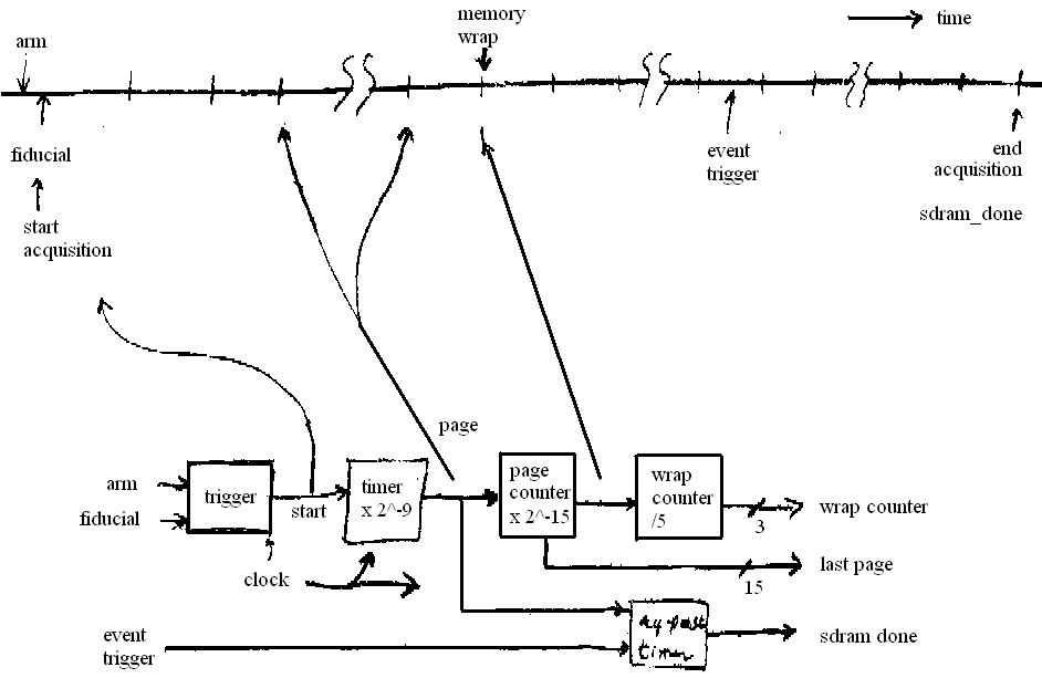
There is on-board SDRAM memory of 32 Mbyte in the current Opal Kelly board. The memory control logic uses it as a continuously written circular buffer where data written past the end of the memory are wrapped to the beginning. After an event trigger, memory continues to be written for about half the memory capacity in order to capture data both before and after the event. At a 40-MHz sample rate, the 16 Mword capacity of the memory maps to 0.43 s acquisition time. Because events can happen at any point of the memory cycle, the end of a write can be anywhere, and restoring the temporal order of the data entails unwrapping the memory at the appropriate point.
In order to record I and Q components of the IF2 signals, there are an odd number of multiplexed signals input to the memory. We are using five multiplexed signals. Because that number is greater than one, there is undersampling of the data, and because the number is odd and greater than one, and because the capacity of the memory is a power of two, the signals and quadrants do not align on successive wraps. For this reason, the number of wraps is counted so that the unwrapping can restore signal and quadrant alignments. If 'ch' is the number of channels, then quadrant and signal alignments repeat after 4 × ch = 20 wraps, so wraps need be counted modulo 4×ch only.
An SDRAM page is pagesize = 512 words. A page counter in logic counts pages and records the page at which acquisition stopped. This number is retrieved so that the recorded data can be unwrapped. The time of the event trigger is not known exactly, but is known to be between half the memory capacity samples earlier than the end of acquisition, and one page before that. So this localizes the event to pagesize samples.
The logic and Matlab software are both programmed for the 32-Mbyte size, although the use of parameters and localparams in logic, and symbols in Matlab code, go part way towards making the code non-specific to the memory size.
Unlike in Hengjie's use of SDRAM, the entire memory is uploaded every access. If not all is needed, it is up to the host to cull the unwanted parts. Improvements in the Matlab code have made the process quite a lot faster, so the volume of data is less of an issue (at least in Matlab). The Matlab code plots all or part of the data, although it is undersampled for large time spans.
Data may optionally be written to a Matlab .mat file. When selected, the file written is given a name constructed from the current date and time: yyyy-mm-ddThhmmss.mat, although saving the data is mandatory if the rf is tripped. Along with the circular buffer data, a representation of the state of the rf controller is also saved. Loading that file restores the two variables buf, which contains the contents of the circular buffer, and state which contains the state information in a structure whose elements echo the names of the functions of the rf API in rfboard.m. The variable buf is a one-dimensional int16 array containing the sequence of multiplexed samples from the five channels. It is unwrapped, and the first sample is the 'I' quadrant of the first channel.
Off-line time-domain plots of dumps can be had using the function CircBufPlot (type help CircBufPlot), and frequency-domain plots are generated by CircBufSpect (type help CircBufSpect).
There are two Verilog modules that manage control of the SDRAM. These are:

Initialization of the record_len field is not implemented in this version.
elapsed = wrapctr*memsize+pagectr*pagesize.So the end of the buffer is sample elapsed-1, and the beginning is elapsed-memsize (in words). The bottom line is that the first zeroth quadrant of the v-th channel has location indexv = modulus(-4*v - (elapsed - memsize) + 6, 4*ch). From there, the I samples of that channel occur every 2*ch samples thoughout the buffer. The Q samples of that channel also occur every 2*ch samples, but following the I samples by 'ch' samples.

As of this writing there are still issues with the logic and/or Matlab software associated with the circular buffer.