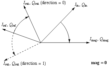
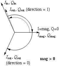
This module takes as an input an I/Q vector and outputs a prescribed reference vector rotated through the same angle or the opposite angle. It has two cordic blocks that work in parallel and without ever recording the angles through which the vectors are rotated. It works in all four quadrants and the outputs are optionally registered. The magnitude of the first vector and busy and done outputs are also available, but reset and enable inputs are not. The source is relatively simple, compact, and portable.

The prescribed vector to be rotated to the output vector can be specified in either of two modes. The first is that it is specified by the two input ports Iref and Qref. The parameter mag must be zero in this case. The figure shows how the vector (Iin, Qin) is rotated to the real axis while input the vector (Iref, Qref) is rotated through the same angle to the vector (Iout, Qout). The output port Imag returns the magnitude of the vector (Iin, Qin) (times 1.65).

In the second mode, where mag > 0, the input vector (Iin, Qin) is replaced by vector (mag, 0} determined by the mag parameter. That vector is then rotated by the angle of the vector (Iin, Qin). The output port Imag again returns the magnitude of (Iin, Qin).
The direction parameter sets whether the reference vector is co-rotated, or counter-rotated with the input vector (Iin, Qin).
Ports | Parameters | Notes | Example
| clk | input | The clock input. |
| rest | input | The reset input. |
| go | input | Initiates the rotation. Can be a multi-bit trigger. |
| gonow | input | Asserted for one clock cycle when all trigger events in the vector go have occurred. |
| quad | input | A two-bit quadrant fiducial. |
| Iin | input | The I (in-phase) input. This signal and Qin provide a phase reference through which the reference vector is rotated. Its bit width is given by the width parameter. |
| Qin | input | The Q (quadra-phase) input. This signal and Iin provide a phase reference through which the reference vector is rotated. Its bit width is given by the width parameter. |
| Iref | input | The signal I input. This signal and Qref, when mag is zero, are rotated through the angle of Iin, Qin. Its bit width is given by the width parameter. |
| Qref | input | The signal Q input. This signal and Iref, when mag is zero, are rotated through the angle of Iin, Qin. Its bit width is given by the width parameter. |
| gonow | output | Pulse that indicates when the multi-level trigger (go) fires to start the calculation. |
| Iout | output | The I component of the output vector. Its width is one greater than the width parameter to avoid overflow. |
| Qout | output | The Q component of the output vector. Its width is one greater than the width parameter to avoid overflow. |
| IoutN | output | The twos-complement negative of Iout. |
| QoutN | output | The twos-complement negative of Qout. |
| Imag | output | A diagnostic output containing, along with Qmag, the result of the rotation of the input vector (Iin, Qin) to the real axis. |
| Qmag | output | A diagnostic output containing, along with Imag, the result of the rotation of the input vector (Iin, Qin) to the real axis. |
| out | output | The four outputs Iout, Qout, IoutN, and QoutN multiplexed using the quadrant fiducial. |
| busy | output | Indicates that a rotation is in progress. |
| done | output | Indicates that a rotation has completed and the output data are valid (see the note below). |
| w1 | 16 | Bit width of the Iin and Qin inputs. The outputs Imag and Qmag are of width one larger. |
| w2 | w1 | Bit width of the Iref and Qref inputs. The outputs Iout, Qout, IoutN, QoutN, and out are of width one larger. |
| steps | w1 | The number of clock cycles through which the Cordic calculation runs. |
| gobits | 1 | The number of trigger bits of the go input. |
| mag | 0 | When nonzero, provides the (real) reference level that is rotated to the phase of the I and Q inputs. The inputs Iref and Qref are ignored. When zero, the input Iref, and Qref together is the vector that is rotated through the angle of Iin and Qin. |
| direction | 0 | Selects the direction, co-rotating (0) or counter-rotating (1), that the reference vector given either by (mag, 0) or (Iref, Qref) is rotated. |
| registered | "no" | When '"yes"', the I and Q outputs are registered. With any other value the outputs are unregistered. |
localparam	w1 = 16, w2 = 18;
wire	signed	[w1-1:0]	Iin, Qin;
wire	signed	[w1  :0]	Imag, Qmag;
wire	signed	[w2-1:0]	Iref, Qref;
wire	signed	[w2  :0]	Iout, Qout, IoutN, QoutN, out;
wire				go, gonow, busy, done;
wire		[1   :0]	quad;
CoRotator
    #(.w1(w1), .w2(w2), .steps(15), .direction(1'b0), .registered("yes"))
    cr1 (
        .clk(clk),		.go(go),
        .quad(quad),		.gonow(gonow),
        .Iin(Iin),		.Qin(Qin),
        .Iref(Iref),		.Qref(Qref),
        .Iout(Iout),		.Qout(Qout),
        .IoutN(IoutN),		.QoutN(QoutN),
        .out(out),
        .busy(busy),		.done(done)
    );