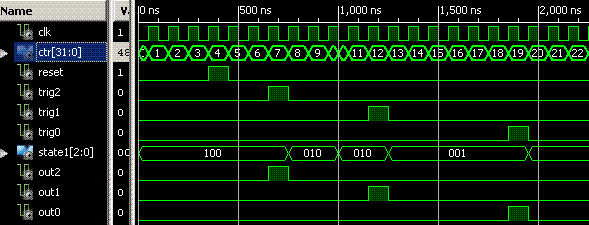
This module implements a linear state machine, i.e., a state machine that steps unidirectionally through a finite sequence of states. A vector of triggers gates the machine from one state to the next. The bits of a vector of outputs is pulsed when its corresponding state is being gated by its trigger bit to the next state. Finally a vector of state bits has bits indicating in what state the machine resides. Thus each of these vectors has as many bits as the machine has states. The diagram illustrates a four-state instance of this module.

The implementation is relatively simple for the reason that there is no encoding of the states. A state is represented by a lone true bit of a state vector, where there are as many possible states as there are bits of the vector.
Ports | Parameters | Notes | Example | Timing diagram
| clk | input | The clock input. |
| reset | input | The reset input restores the idle state. |
| trig | input | A vector of count triggers. |
| out | output | A vector of count pulse outputs. |
| state | output | The state of the state machine as a vector of count bits: 100... for idle, 0100... for first trigger, ..., ...001 for the final armed sate. |
| count | 2 | The number of states, trigger bits, and output bits of the instance. |
Imagine that a sequence must be started in reponse to an operator command cmd, but it must be timed following a global fiducial gfid synchronizing accelerator systems, following a zero-bunch fiducial bfid, and following a quadrant fiducial qfid. The instance looks like this:
wire          	reset, FinalTrigger;
Trigger #(.count(3)) trig_inst (
	.clk(clk),			.reset(reset),
	.trig({gfid, bfid, qfid),	.out(FinalTrigger)
);
Note that the vector of triggers is arranged left to right, and that FinalTrigger is assigned to the final output out[0] according to the rules of Verilog.
