Doubles the data rate and upconverts the 10-MHz IF frequency to 50 MHz prior to digital-to-analog conversion. A filter is employed to remove 10- and 70-MHz lines.

Ports | Parameters | Notes | Example
| clk1f | input | The clock input. |
| clk2f | input | The double-rate clock input. |
| in | input | The input data stream. |
| out | output | The double-rate output data stream. |
| dw | 14 | The bit width of the data stream. If this parameter is changed, the 1/sqrt(2) constant coded into the module may need to be changed. |

Up conversion is conceptually interleaving the original data samples with zero samples, which multiplies the sample frequency and consequently the size of the frequency space. The signal spectrum is replicated in the remainder of the upconverted frequency space. In our application, the signal spectrum has lines at 10 and 30 MHz, which are replicated to additional lines at 50 and 70 MHz. The line at 50 MHz is the wanted line, while the lines at 10, 30, and 70 MHz are unwanted.
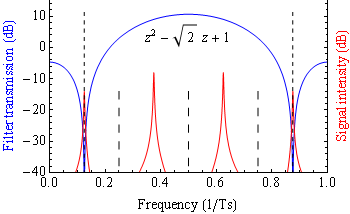
So the function of the filter is to weed out the unwanted lines in the signal spectrum (red), in this case at 10 MHz and 70 MHz. The lines at 30 and 50 MHz are kept. (The 30-MHz line cannot be removed independently of the 50-MHz line because this is a real-valued data stream.) The filter response shown in blue, which is implemented in this module, is the simplest filter that has this property.
In the graph, Ts is the up-converted sampling interval.
In the block diagram, blocks to the right of 40-MHz select block are clocked at double the incoming sample rate.
wire			clk_40, clk_80;
wire	signed [14:0]	din, dout;
UpConv #(.dw(15)) UpConversion (
	.clk1f(clk_40),	.clk2f(clk_80),
	.in(din),	.out(dout)
);