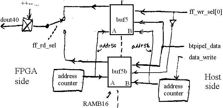
Dual 1024-word tables used for feedforward setpoints implemented using dual-port memories. Arbitrary waveforms may be loaded and read out. At any one time, either of the tables may be read out to logic, and the rate at one is read out is selectable over a wide range. On the host side, at any one time either table may be written to. The module also provides timing signals that facilitate synchronization the the output to other sequences. One in particular is that it outputs a pulse at about 20% of its sweep intended for synchronizing capture of signals during the sweep.

Ports | Parameters | Notes | Example | Diagram
| clk | input | The clock input. |
| reset | input | A reset input. |
| go | input | |
| quad | output | A two-bit word that indicates in which quadrant the current sample of the I, Q, -I, -Q ... stream resides. |
| zoom | input | Selects a time scale at which to output the table. It selects one of 32. |
| dout40 | output | The feed forward output of the module in the I, Q, -I, -Q ... sequence. |
| busy | input | When asserted, indicates that a ramp is in progress. |
| done | input | Asserted for one clock cycle to indicate that a ramp has completed. |
| sclk | input | A sample clock indicating that a new sample output by the table has become valid. |
| addr5a | output | The 11-bit address of the samples output by the module. The second lsb is used to change the sign of the output during the generation of the ++-- ... sequence. |
| sampletick | output | A timing pulse output a given delay following the end of a sweep. |
| samplevalid | output | Indicates that during the current or previous sweep, the sampletick output pulse was output a given delay following the start of the sweep. The delay timer is started at the end of each sweep. If a new sweep has not started by the end of the delay, then samplevalid is deasserted. |
| ff_wr_sel | input | Selects to which of the two buffers data are written. |
| ff_rd_sel | input | Selects to which of the two buffers data are read and output to dout40. |
| ti_clock | input | The host-interface clock. |
| data_write | input | Initializes host write logic (addr5b address counter) in preparation for writing to the buffers. |
| buf_dac_write | input | When high, the host has placed valid data onto the data pipe (btpipeI_data). |
| btpipeI_data | input | The port carrying data from the host to be written to the dual-port memory. |
| dw | Bit width of the output port dout40. |
| iw | Bit width of the interval timer that times the clocking of the samples output by the module. |
| gb | Number of bits of the goport, which is equal to the number of trigger levels starting ramps. |
| sampledelay | Delay in I/Q sample pairs following the end of a sweep at which time the sampletick output is pulsed. |
localparam			ssd = 26;
wire			reset, clk_40, fb_en, data_write
wire	signed [14:0]	fb_out;
wire		[ssd-1:0]	cnt16k;
ffSetpointTable	#(.w1(15), .w2(ssd))	ffTable(
	.clk(clk_40),
	.reset(count_reset),
	.go(go),
	.quad(quad),
	.zoom(zoom),
	.dout40(dout40),
	.sclk(sclk),
	.addr5a(addr5a),
	.sampletick(sampletick),
	.samplevalid(samplevalid),

	.ff_rd_sel(ff_rd_sel),

	// ff setpoint table in two buffers; ep 80
	.ti_clk(ti_clk),
	.data_write(data_write),
	.ff_wr_sel(ff_wr_sel),
	.buf_dac_write(buf_dac_write),
	.btpipeI_data(btpipeI_data)

);