Class for model-based calibration of equatorial telescope mounts
This note documents a physical-model based pointing model generally useful for equatorial telescopes, and a .net class for its implementation. This model takes into account polar axis misalignment, a couple of axis misalignments, and RA and declination offsets. Tests with my Atlas mount over a modest portion of the sky have shown its accuracy to be a few arc minutes or better.
- Introduction
- The mathematics of the model
- Relating celestial and mount coordinates
- Computing mount alignnment/calibration parameters
- Implementation
- Calibration of the mount's pointing model
- Parameters of the mount's pointing model
- Setup/calibration graphical user interface
- Field tests
- References
Introduction
Angular coordinates returned by telescope mounts never coincide with apparent coordinates because of imperfections of the mounts mechanical errors, position encoding, flexure, and other factors. But by measuring a mount's angular coordinates when pointing to a set of objects of known celestial coordinates, a mapping between the two coordinates can be determined with reasonable accuracy. One way to do this is by interpolation, where a number of objects are measured in directions scattered about the sky, and mount coordinates of objects of interest are interpolated between nearby measured objects.
In general, coordinate discrepancies are dominated by a relatively small number of alignment and calibration issues that, when the most important are known, permit a usefully accurate model-based approach to relating mount and apparent coordinates. By physical model is meant that parameters characterizing the model correspond to physical characteristics of the mount. An example is the offset of the right-ascension coordinate readback having mechanical and/or electronic cause. The accuracy of coordinate conversions depends both on the accuracy of parameters measured, and on how well in general the model characterizes telescope pointing. The latter, I think, can be rather good with relatively simple models and today's mounts. Thus I think there is a better way to calibrate telescope/mount pointing than via brute force coordinate interpolation.
 So the immediate problem is to construct a reasonably simple model of mount pointing. One element of any useful model was mentioned earlier: an offset of the right ascension readback. This, and the corresponding offset of the declination readback, account for two elements of the model and two calibration parameters. A second major element of any useful model of telescope pointing is the direction towards which the polar axis points. Two parameters are needed to specify this direction, e.g., right ascension and declination, which account for a second pair of parameters that partly characterize the model. A fifth parameter is the angle between the right ascension and declination axes, and a sixth is the angle between the telescope optical axis and the declination axis. These parameters all have familiar physical meaning.
Other factors that influence mount (telescope) pointing include flexing of the mount and OTA under their weight, nonlinearity of the position encoders, gear backlash, temperature-dependent flexing, stepping-motor slippage, sinking of tripod feet, periodic error, etc. Depending on the telescope and mount these factors may or may not be very important, but they are also rather more difficult to model. Others have done it I know, but in order to have a tractible project from my perspective, I did not include any of these factors in the model, although I am working on a flexure pointing model.
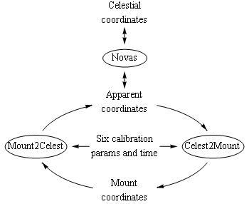
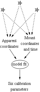 So the pointing model I developed and programmed has six parameters, and with these parameters known, mount right-ascension and declination settings are computed freely from astrometric coordinates and vice versa as illustrated in the figure. Those coordinate conversions are, in principle, valid over the entire sky, although accuracy may not be uniform. That there are a relatively small number of parameters means that a relatively small number of measurements are required to determine them. Measurements are done in the familiar way by centering the scope on a set of stars of known apparent coordinates and recording the mount's coordinates for each. This provides six measurements (two mount coordinates for each star's celestial coordinates), which are then inverted to obtain the six calibration parameters.
The mathematics of the model
This section describes the mathematics of the mount pointing model in terms of coordinate rotations in the context of the Lie group SO(3) and its associated Lie algebra so(3) [2]. There are a couple of parts to the implementation of the model, the first being to relate in a mathematical way apparent coordinates and mount coordinates for any given set of mount parameters. With this done, the computational steps illustrated in the first figure, Mount2Celest and Celest2Mount when mount parameters are known, are implemented relatively easily. The second problem, that of calculating mount parameters from a set of measurements of calibration stars, would be somewhat more involved, but is handled globally as a function-minimization problem as discussed earlier.
Relating celestial and mount coordinates
First define a basis set of the Lie algebra so(3), the vector $\vec{\sigma} = (\sigma_x, \sigma_y, \sigma_z)$ of three 3-by-3 matrices
\[ \sigma_x = \left[ \begin{array}{ccc} 0 & 0 & 0 \\ 0 & 0 & -1 \\ 0 & 1 & 0 \end{array} \right] \]
\[ \sigma_y = \left[ \begin{array}{ccc} 0 & 0 & 1 \\ 0 & 0 & 0 \\ -1 & 0 & 0 \end{array} \right] \]
and
\[ \sigma_z = \left[ \begin{array}{ccc} 0 & -1 & 0 \\ 1 & 0 & 0 \\ 0 & 0 & 0 \end{array} \right] \]
Any element $v$ of the Lie algebra is a superposition of the three matrices through the three-vector of real parameters $\vec{v} = (v_x, v_y, v_z)$ via
\[ v = v_x \sigma_x + v_y \sigma_y + v_z \sigma_z = \vec{v} \cdot \vec{\sigma} \]
where $\cdot$ is the inner product, and the $x$, $y$, and $z$ directions from the Earth's perspective are through the celestial equator at the meridian, through the celestial equator tangential to the Earth, and through the celestial pole, respectively. Each such superposition maps to an element of the Lie group through matrix exponentiation
\[ V = e^v = e^{\vec{v} \cdot \vec{\sigma}} = e^{v_x \sigma_x + v_y \sigma_y + v_z \sigma_z} \in SO(3) \]
where the direction of $\vec{v}$ is the axis of rotation, and the magnitude of $\vec{v}$ is the angle through which $V$ rotates. Matrix exponentiation is defined through the power series of the exponential function. A vector $\vec{w} = (w_x, w_y, w_z)$ is mapped to a corresponding vector $\vec{w}^\prime$ by matrix product:
\[ \vec{w}^\prime = V \cdot \vec{w} \]
With those mathematical preliminaries out of the way, the problem is to understand how the celestial sphere is transformed through the Earth's rotation, mount alignment errors and calibration offsets, and mount polar-axis rotation, to the celestial sphere relative to the scope's OTA perspective. So we might regard the north pole of the celestial sphere as the $z$ axis, while the axis of the scope from its perspective is regarded as its own $z$ axis. So we want to step through the various transformations from one to the next. There are several perspectives along the way.
- The first transformation is from the fixed celestial sphere to the perspective fixed to the rotating Earth. Vectors are transformed by the matrix $e^{\omega t \sigma_z}$, where $\omega = 2\pi/$sidereal day and $t$ is time.
- The next is the transformation to the perspective of the polar axis of the mount, which is offset from the north celestial pole by some angle and direction, but still fixed to the Earth. This transformation is characterized by a rotation about some axis fixed to the Earth and oriented through the equator. Thus it is the transformation matrix $e^{-\delta}$, where $\delta$ is the Lie-algebra-valued $\delta = \delta_x \sigma_x + \delta_y \sigma_y$, and $\delta_x$ and $\delta_y$ are real parameters specifying the polar-axis misalignment. They account for two parameters of the calibration model.
- The third transformation corresponding to tracking is to the perspective fixed to the counter-rotating polar axis. It is given by the time-dependent matrix $e^{-\omega t \sigma_z}$. The tracking rate $\omega$ is assumed perfectly matched to the Earth's rotation.
- The fourth transformation accounts for the departure of the declination axis from perpendicular to the polar axis. The angular error $\alpha$ determines the transformation matrix $e^{-\alpha \sigma_x}$ to the perspective of the slightly tilted declination axis.
- The fifth transformation accounts for rotation of the right ascension of the mount by the right-ascension reading $RA$ of the mount, plus an offset $r$. It has matrix $e^{(-RA + r) \sigma_z}$. The parameter $r$ is a parameter of the calibration model.
- The sixth transformation accounts for a rotation of the declination axis of the mount by the mount's declination readout $Dec$ plus an offset $d$. It has matrix $e^{(-Dec + d) \sigma_y}$; $d$ accounts for a parameter of the calibration model. Note that $Dec$ in this expression is actually codeclination measured from the pole and not the equator.
- The seventh transformation is to the perspective of the scope OTA given an angular error $\gamma$ between its axis and the declination axis. Its transformation matrix is $e^{-\gamma \sigma_x}$; $\gamma$ is the last parameter of the calibration model.
These maps are concatenated to the map
\[ M(RA, Dec; \delta_x, \delta_y, r, d, \gamma, \alpha) = \cdot e^{-\gamma \sigma_x} \cdot e^{(-Dec + d) \sigma_y} \cdot e^{-\alpha \sigma_x} \cdot e^{(-RA + r) \sigma_z} \cdot e^{-\omega t \sigma_z} \cdot e^{-\delta_x \sigma_x - \delta_y \sigma_y} \cdot e^{\omega t \sigma_z} \]
which maps vectors from the fixed celestial sphere to vectors viewed from the telescope's perspective when oriented by the mount with coordinates $RA$ and $Dec$. A vector pointing to a star with apparent coordinates $ra$ and $dec$ (codeclination) is
\[ star = e^{ra \, \sigma_z} \cdot e^{dec \, \sigma_y} \cdot \hat{z} \]
where $\hat{z}$ is the unit vector in the $z$ direction. Note that if all six parameters are zero, $ra = RA$, and $dec=Dec$, then the mount is perfectly aligned and $M$ maps the star back to the $z$ axis, i.e., the star is on the center of the telescope's field of view. But when the six alignment/calibration parameters are not all zero, and known, when the star is centered in the scope's field of view, the matrix arithmetic of the equation
\[ \hat{z} = M \cdot star = M(RA, Dec; \ldots) \cdot e^{ra \, \sigma_z} \cdot e^{dec \, \sigma_y} \cdot \hat{z} \]
holds, which provides a correspondence between the mount coordinates $(RA, Dec)$ and apparent coordinates $(ra, dec)$. Thus this equation provides a means by which apparent coordinates are mapped to scope coordinates (Celest2Mount) and scope coordinates are mapped back to apparent coordinates (Mount2Celest).
The two directions are not equally easy to calculate. When starting from mount coordinates $(RA, Dec)$, $M$ is directly calculated, and inverted, the result of which is used to calculate the vector $star$. From there it is just algebra and trigonometry to calculate the apparent coordinates $ra$ and $dec$ from $star$. The inverse is formulated as a function-minimization problem and is more involved for that reason.
While the pointing state of the mount [4] has no impact, at least for a perfect mount, on the direction towards which the OTA points, it does affect the OTA's orientation about that axis modulo 180 degrees. But when the mount is not perfect, i.e., when not all the parameters of the mount's pointing model are zero, then the pointing state of the mount does affect the direction towards which the OTA points. For example, a telescope on a perfect mount perfectly aligned with the pole and pointing towards the pole also points toward the pole in the second pointing state. But when $\alpha$ is not zero, i.e., the OTA axis is not perpendicular to the declination axis, the OTA no longer points toward the pole, and the axis in the two pointing states points to directions on opposite sides of the pole. So the pointing state is an important part of coordinate conversions and calibration of real mounts.
Computing mount alignment/calibration parameters
The problem of computing the calibration parameters from star measurements is computationally more involved. The idea is that we start with a set of measured mount coordinates (including sidereal time and pointing state) of stars whose apparent coordinates are known.
\[ \left[ (RA, Dec)_{apparent}, \, (RA, Dec, \, pointing \, state)_{mount} \right]_{star_1} \]
\[ \left[ (RA, Dec)_{apparent}, \, (RA, Dec, \, pointing \, state)_{mount} \right]_{star_2} \]
\[ \left[ (RA, Dec)_{apparent}, \, (RA, Dec, \, pointing \, state)_{mount} \right]_{star_3} \]
As was mentioned earlier, we need at least three star measurements so that we have at least as many measurements as parameters to be determined. Each pair of apparent coordinates gives us a star vector, which is mapped by $M$ to the perspective of the scope.
\[ scope \, vec = M(RA_{mount}, Dec_{mount}; \, params \ldots) \cdot e^{RA_{appar} \, \sigma_z} \cdot e^{Dec_{appar} \, \sigma_y} \cdot \hat{z} \]
If the calibration parameters are exact (and the model itself is accurate) then the scope vector (lhs) is at the center of the scope's field of view (its $z$ axis). If not then there is an angular difference (an error) between that vector and the $z$ axis. The three angular errors corresponding to the three stars are used to construct a mean square error, i.e., an objective function for function minimization. The six alignment/calibration parameters are varied so as to find that minimum angular error. With three stars there are six measured numbers that exactly determine the six calibration parameters. That is the idea behind the calculation the mount's calibration parameters.
Implementation
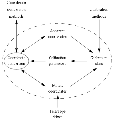
This implementation consists of the core pointing model in the class PointingModel and the setup window in the class MCSetupForm, which mediates entry of calibration stars. The core methods of PointingModel are the coordinate-conversion methods, which translate between J2000 coordinates or apparent coordinates, and mount coordinates. A second group consists of methods for calibration. These methods are called as known calibration stars are centered in the scope's field of view. MCSetupForm provides an interface to these methods, allowing the user to add, delete, and otherwise manipulate the set of calibration stars.
While PointingModel can be used independently, it is automatically instantiated when MCSetupForm is instantiated.
' connect to a telescope driver
dim scope as Telescope = New Telescope(Choose("Telescope"))

' create the setup form and the pointing model instances
Dim sf as MCSetupForm = New MCSetupForm(scope)

' fetch a pointer to the pointing model
dim pm as PointingModel = sf.pm
The user uses the setup form to calibrate the mount, and the pointer pm is now available for coordinate transformations. When connecting to a different telescope driver, just close the current pointing-model setup form, create a new form, and redefine pm.
In a driver accepting J2000 coordinates, the SlewToCoordinates function, for example, transforms the incoming J2000 coordinates to the mount coordinates that point the OTA in the cooresponding apparent direction, and calls the real driver's slew method.
Public Sub SlewToCoordinates(ra as double, dec as double)

    ' construct a CatEntry3 structure for the target
    Dim cat as new CatEntry3
    cat.RA = ra : cat.Dec = dec

    ' determine the pointing state at the target
    Dim pstate as pierSide = scope.DestinationSideOfPier(ra, da)

    ' compute the mount coordinates through the pointing model
    Dim crds() As Double = pm.Celest2Mount( _
        cat, _
        EquatorialCoordinateType.equJ2000, _
        scope.SiderealTime, _
        pstate _
    )

    ' submit the slew to the real driver
    scope.SlewToCoordinates(crds(0), crds(1))

End Sub
Note that there is the potential for a pointing error if the the mount actually positions the OTA on the opposite pointing state as anticipated by the the example slew method above. This can happen if the user implements an alternate scheme for managing flips than is implemented by DestinationSideOfPier, or, for coordinates near the meridian, due to mount misalignments mount and apparent coordinates are on opposite sides of the meridian. One can self-consistently calculate pstate and crds(), but there may not always be a solution near the meridian.
This section outlines an exposed subset of the properties and methods of the PointingModel class.
Various mount control functions and properties
Most arguments and return values of public functions are in hours and degrees. Internally all quantities are in radians.
- Constructor
- This function accepts as argument a pointer to the telescope driver.
The coordinate-conversion functions Celest2Mount and Mount2Celest are overloaded for various types of coordinates. These are the core methods of the usage side of this class.
- Celest2Mount
-
Used to compute mount coordinates from celestial coordinates, using the mounts alignment/calibration parameters. It is overloaded so that it may be provided either J2000 or apparent coordinates via a CatEntry3 structure or array of two doubles, respectively. Similarly, they are overloaded so that sidereal time and pointing state are either provided as arguments, or are provided by the mount. Note that these conversions depend on the sidereal time because the orientation of the scope's polar axis is fixed to the earth and consequently rotating relative to the celestial sphere.
This function returns mount coordinates when given apparent coordinates.
Public Overloads Function Celest2Mount( _
    ByVal apparentoordinates() As Double, _
    ByVal siderealtime As Double, _
    ByVal pointingstate As PierSide _
) As Double()
This method takes as an argument J2000 coordinates in a CatEntry3 structure.
Public Overloads Function Celest2Mount( _
    ByVal cat As CatEntry3, _
    ByVal coordinatetype As EquatorialCoordinateType, _
    ByVal siderealtime As Double, _
    ByVal pointingstate As PierSide _
) As Double()
The coordinate type of the coordinates in the CatEntry3 may be specified, but on J2000 coordinates is supported.
This method is the same as the previous method except that the time and pointing state are taken from the mount.
Public Overloads Function Celest2Mount( _
     ByVal cat As CatEntry3, _
     ByVal crdtype As EquatorialCoordinateType _
) As Double()
- Mount2Celest
Used to compute celestial coordinates from mount coordinates, sideral time, and pointing state using the mount's current alignment/calibration parameters. Returns either J2000 or apparent coordinates as a list of doubles depending on the value of an optional EquatorialCoordinateType argument. It is also overloaded so that the mount provides the mount coordinates, sidereal time, and pointing state.
This form accepts explicit arguments for sidereal time, pointing state, mount coordinates, and celestial coordinate type, and returns celestial coordinates.
Public Function Mount2Celest( _
    ByVal siderealtime As Double, _
    ByVal pointingstate As PierSide, _
    ByVal mountcoordinates() As Double, _
    Optional ByVal crdtype As EquatorialCoordinateType = EquatorialCoordinateType.equJ2000 _
) As Double()
This form gets the first three arguments directly from the mount.
Public Function Mount2Celest( _
    Optional ByVal crdtype As EquatorialCoordinateType = EquatorialCoordinateType.equJ2000 _
) As Double()
Calibration of the pointing model
There are a small handful of functions for the mount-calibration side of the class PointingModel. Stars of known coordinates are centered in the field of view or on cross hairs. The mount coordinates, together with the catalog coordinates are recorded and used to calibrate the mount pointing model.
- AddStar
-
This function accepts astrometric coordinates of an object that has been centered in the scope's field of view and uses it, and the mounts coordinates, pointing state, and sidereal time, to calibrate the mount's pointing model. It internally adds that object to a list of calibration stars that are all used to calibrate the mount each time the function is called. Overloaded versions accept coordinates as either a CatEntry3 structure for astrometric (J2000) coordinates or an array of (two) doubles representing apparent coordinates. Once this function is called three or more times with centered stars, the mount is nominally calibrated. It also requires as argument a callback function that during a calculation may periodically be provided an integer and double argument representing an iteration count and the current value of object function of the function minimization, respectively.
This form accepts a CatEntry3 structure with J2000 coordinates for the observed star. Mount coordinates, pointing state and sidereal time are taken directly from the mount.
Public Function AddStar( _
    ByVal cat As CatEntry3, _
    ByVal cb As StatCallback, _
    Optional ByVal threshold As Double = 1, _
    Optional ByVal iter As Integer = 25 _
) As Double()()
This method accepts apparent coodinates (which includes refraction) of the observed star. Mount coordinates, pointing state, and sidereal time are again taken directly from the mount.
Public Function AddStar( _
    ByVal apparentcoordinates() As Double, _
    ByVal cb As StatCallback, _
    Optional ByVal threshold As Double = 1, _
    Optional ByVal iter As Integer = 25 _
) As Double()()
This is a low-level form of the function. The argument so is a structure representing the observation of a star (see below).
Public Function AddStar( _
    ByVal so As StarObs, _
    ByVal cb As StatCallback, _
    Optional ByVal threshold As Double = 1, _
    Optional ByVal iter As Integer = 25 _
) As Double()()
The two-element jagged-array return value of these methods consist of 1) a list of the calculated mount parameters: two for one star, four for two, and six for three or more calibration stars; and 2) a list consisting of the final value of the object function, and an iteration count. The model parameters of the PointingModel object are updated internally. It is the final value of the object functions that is most useful determining that the calculation converged to a meaningful solution.
When only one star observation is present at the time of a call to AddStar, then only the right ascension and declination offsets (raos and decos) are computed. If two stars are registered, then those two parameters plus the deltax and deltay parameters for the polar axis are computed. In either of these two cases, there is insufficient information to compute these parameters, and the numbers returned represent only values that result in the best pointing of the scope to the calibration stars given. But if three or more calibration stars are registered, then all six alignment/calibration parameters are computed to the accuracy permitted by the quality of the star observations and the model.
This inversion is performed as a function-minimization problem. That it is a function-minimization problem means that it is possible to use additional stars to reduce errors. Three stars typically results in a perfect fit of the calibration stars to the measured positions because there are six unknown parameters fit to six measurements. Thus no information about the quality of the fit is available from a three-star calibration. But additional calibration stars provide additional measurements fixing the six parameters, and new information about the quality of the fit results. There is evidence that additional stars improve accuracy, and that four stars is a considerably better choice than three.
- RemoveStar
Removes the selected star from the internal list of calibration stars. It recalculates the mount's calibration, but if there are no stars in the list, then a list of two nulls is returned.
Public Function RemoveStar( _
    ByVal index As Integer, _
    ByVal cb As StatCallback, _
    Optional ByVal threshold As Double = 1, _
    Optional ByVal maxiter As Integer = 25 _
) As Double()()
where index is the zero-based index of the star to be removed.
- ClearStars
Deletes all calibration stars in the internal list.
Public Sub ClearStars()
- StarCount
The number of stars in the list of calibration stars.
Public Function StarCount() As Integer
- StarObs structrure
Structure representing the observation of a star.
Structure StarObs
    Dim RAApparent As Double    ' in hours
    Dim DecApparent As Double   ' in degrees
    Dim SiderealTime As Double  ' in hours
    Dim RAMount As Double       ' in hours
    Dim DecMount As Double      ' in degrees
    Dim pointingState As PierSide
    Dim azimuth As Double
    Dim elevation As Double
End Structure
It contains the apparent coordinates of the object (including refraction), and the mount's coordinates, pointing state, and sidereal time at the time of the observation.
It has a method ToString that accepts an optional new line string.
Shadows Function ToString( _
    Optional ByVal newline As String = vbNewLine _
) As String
It also has a shared function length that returns its length in bytes (60).
Shared Function length() As Integer
- ToString
A ToString function that returns a string containing the model parameters.
Parameters of the mount's pointing model
The mount alignment/calibration parameters are fundamental properties of the pointing model of the telescope. They are all expressed in radians.
- deltax, deltay
- These two parameters model polar-axis misalignment, corresponding to the parameters $\delta_x$ and $\delta_y$ respectively of the math section. The quantity $\sqrt{\delta_x^2+\delta_y^2}$ is the angle between the mount's polar axis and the pole, with the two parameters defining an equatorial vector. These parameters can be used to reorient the polar axis to the celestial pole.
- raos, decos
- These parameters represent the offsets between the mount's right-ascension and declination readings and the actual orientation of the mount's axes. They correspond to the parameters $r$ and $d$ in the math section.
- gamma
- Angle between the OTA optical axis and the perpendicular to the mount's declination axis. It corresponds to the parameter $\gamma$ in the math section.
- alpha
- The angular error between the right ascension and declination axes. It corresponds to the parameter $\alpha$ in the math section.
Although there are other ways to do this, e.g., polar alignment by the drift method [5], these parameters measured by the calibration process can in principle be used to physically correct corresponding physical errors in the mount's alignment.
Setup screen
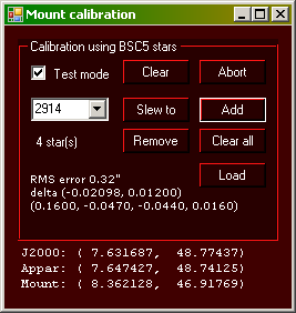
The illustration to the right is of part of a setup screen implementing the calibration functions. At the bottom are displayed, starting from the bottom, the current raw mount coordinates, the apparent coordinates, and J2000 coordinates towards which the mount (OTA) is pointed inferred by the mount calibration. When the mount is uncalibrated so that the calibration parameters are all zero, then the mount coordinates are the same as the apparent coordinates.
Above that are the calibration controls where stars are entered for calibrating the mount. At least three stars from the Yale bright-star catalog [6] are entered numerically in the text box. They should be widely scattered in the sky but not particularly close to the horizon. The astrometric coordinates of these objects are obtained from a catalog. The 'Slew to' button slews the mount to the calibrated position using the current calibration, which may be a zero-, one-, two-, or more-star calibration. Once slewed, the star is centered in the field of view or placed on cross hairs by manually slewing the scope. Then the 'Add' button is pressed, which adds the star as a calibration star and performs the calibration with the current set of calibration stars. The 'Remove' button removes the selected star and the 'Clear all' button clears all stars from the list. The parameters resulting from each calculation become the new set of calibration parameters of the mount (deltax, deltay, raos, decos, gamma, and alpha) and subsequent mount/celestial coordinate conversions use these numbers.
There are a few other useful buttons in that box. The clear button is used to manually clear the calibration parameters, and the abort button is used to stop a calculation that my be continuing due to slow or lack of convergence. The load button loads the latest saved values. Under some circumstances the calibration can be restored this way when the program is closed or it crashes, and is restarted. But knowledge of the calibration stars is not restored.
The text at the bottom of the calibration box has the value of the object function in minutes or seconds of arc at the end of the last calculation, and the computed six calibration parameters. During a calculation, the callback displays an iteration count and the value of the object function, giving an indication of the progress, or lack of it, of the calculation.
Test mode
The test-mode check box is used for off-line testing with a simulator [7]. When checked, the slew buttons, before slewing, insert known test values for the six calibration parameters. This way, slews point the mount to the target stars via the calibrated slew methods with simulated misalignments. The old calibration parameters are subsequently restored. When the calibration calculations are performed with three or more stars, the known calibration parameters are returned. If not, then there is a problem with the interface's usage, choice of stars, convergence, bugs, etc. This mode of operation has been a powerful tool for software development, and the simulator has been an indispensible part of it.
The test mode is also be a useful off-line training tool. I strongly recommend users become familiar with the use of the controls using this feature indoors before attempting to use the driver outdoors with a real telescope.
Field tests
Early tests of the code by calibrating on three stars and slewing to stars on both sides of the meridian and measuring the angular errors from the center of the field of view. In one test, of 27 slews, the root-mean-square error was 2.5 arc minutes without any outliers. The worst case was a 7' error. A couple of other tests were similar.
Another test shows to what degree additional calibration stars improves pointing accuracy. I recorded the apparent coordinates and centered mount coordinates of 22 stars, a data set I used for statistical studies off line. (Two of these stars are outliers, presumably incorrectly identified stars.) While these data provide little guidance about the choice of calibration stars, they provide information about the impact of the number of calibration stars on overall pointing accuracy. I computed rms pointing error of all the stars of the data set when 3, 4, 5, and 6 stars are used for calibration, and all combinations of calibration stars from the data set. Histograms of these errors are shown in the four graphs. They consistently show a spread of the errors that decreases with the number of calibration stars. They also suggest that only three calibration stars may be particularly unreliable and that four is a better choice.
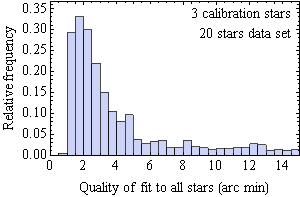

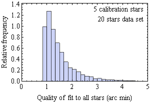

You can see how the quality of the calibrations improves in a statistical sense with increasing number of calibration stars, particularly going from three to four stars. In practice, a resonable choice of calibration stars is not random, but instead the stars are more widely spread in the sky. So these graphs are not necessarily representative of accuracy during normal use. But in another test I did not find a strong correlation of pointing error with a measure of the spread of the calibration stars. Nevertheless, they do suggest more reliable accuracy with more than three stars. Note that the quality of fit is never less that about 0.8 arc minutes. This is presumably indicative of the repeatability of the mount pointing. A fit with all stars as calibration stars produces a fit of 50 arc seconds rms, which is a lower limit given any set of calibrations stars from this data set.
After calibration, it can be seen that with tracking the calibrated readback drifts, as expected, reflecting the existence of error of the mount's alignment, particularly polar alignment. Periodically performing a slew to the calibrated target position brings the calibrated readback back to approximately the target position. This is a way to correct for the tracking errors, although it cannot correct for periodic error.
Installation
- ASCOM platform 6 must be installed [1] with needed telescope drivers.
- The Meta.Numerics package may need to be installed [2], although installation of the dll in the path may be adequate.
- There is a function-minimization DLL provided by me (Bobyqa.dll) to be installed in the path [8].
- The dll for the pointing model and setup form (PointingModel.dll) must be installed in the path.
- For development, the source and project files must be installed in a directory and the two dlls included in the project.
- The one catalog file can be either in the directory of the running application, or in a directory pointed to by the environment variable starcat.
References
- ASCOM, http://www.ascom-standards.org/index.htm.
- Meta Numerics, http://metanumerics.codeplex.com/.
- Wikipedia, Rotation group SO(3), http://en.wikipedia.org/wiki/Rotation_group_SO(3).
- Peter Simpson, Pointing State and Physical Side of Pier for German Mounts (2009).
- N. Towne, Polar alignment by the single-star drift method (2012), http://www.frontiernet.net/~towne56/DriftPolarAlignment/DriftPolarAlignment.html.
- Hoffleit D. and Warren Jr W.H., Yale Bright Star Catalog, 5th Revised Ed. (1991), http://tdc-www.harvard.edu/software/catalogs/bsc5.html.
- EQMOD simulator, http://eq-mod.sourceforge.net/eqaindex.html; part of the EQMOD Project, http://eq-mod.sourceforge.net/introindex.html.
- Function minimization software copyright (©) 2012 Anders Gustafsson, Cureos AB; released under an MIT license; https://github.com/cureos/csbobyqa. Adapted to Visual Studio 2005.
- Patrick Chevalley, Cartes du Ciel, http://www.ap-i.net/skychart (© 2002-2012).
- T. Taki, Matrix Method for Coordinates Transformation, (2003); this document has another presentation on the pointing model.
Nathan Towne
9/2012