|

For several years, before I added 80 meters to my NB6Zep Antenna, I operated that band with a center loaded wire antenna. Those were the days before I discovered antenna computer modeling as an alternative to the cut-n-try methods. I started by pounding a 8 foot ground rod into damp earth at a strategic spot about 5 feet from the base of a tree in my back yard. The limbs of the tree became supports for several experimental antennas used from the 160 to 30 meter bands. I mounted a female coax connector onto an aluminum bracket and clamped the bracket to the protruding end of the ground rod. I soldered my antenna wires to the connector and used tape and sealant around the coax. I had the best results with a straight 33 foot long wire on 40 meters and a similar length of wire center loaded on 80 meters. The center loaded wire I had for 160 meters required to much maintenance, so I did not repair it after it blew down the last time...
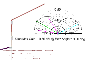
The physical length of an 80 meter 1/4 wave wire is approximately 66 feet, depending on what part of the band it is being cut to. To make this physically shorter, while keeping it electrically a 1/4 wave length, we add inductance to the wire. Traditionally this is accomplished with a coil near the bottom end of the wire, where current is highest (impedances is lowest). Bottom loading has the greatest effect on inductance and the coil can be made the smallest in size. It would be better to move the inductance coil away from where the antenna currents are highest, because this is the spot on the wire where most of the magnetic energy (RF) is produced. Moving the coil away from the end will require the inductance to be greater and therefor the coil to be larger. I determined that 2 coils placed in the bottom half of the wire would be more practical than 1 large coil.
Basic Construction:
The value for both of the coils is 21 uH or about 400 ohms reactance at 3.5 Mhz. The dimensions of the coil I used are 4 inches of BW coil stock #3026, or 4 inches of 8 turns per inch on a 2 inch diameter form. You can make your own coils if you have a 2 inch diameter form (like PVC pipe). 18 to 12 AWG wire will work fine... If the coils are not "perfect" you will be able to compensate later by trimming the top section of wire. The important thing is that the coils be rigid and have strain relief so the inductance does not change during operation. CLICK for DETAIL
The wire sections are cut to a final length of 6 feet for the bottom section, 9 feet for the middle section and start with the last section at 22 feet. After the wire is installed and coax is properly attached to the rod and wire, the top section can be trimmed to provide best SWR (or resonance) at the desired frequency. (The modeled length of the top wire was 18 feet.) I generally use 18 AWG wire for my stealthy antennas.
Like all electrically shortened antennas, it will have a high "Q" and a very narrow band width for operation. It also has a very low impedance at the feed point that would not normally provide a 50 ohm match to the coax line. This is where the bad news about the ground resistance of this system becomes good news for the feed line. I found that my 8 foot ground rod, along with the resistance in 70 feet of 50 ohm coax, returned a low SWR over a 50 Khz section of the band at the frequency I trimmed it for. An RX noise bridge indicated an impedance at the radio of 40 ohms. There is no way to determine what the effects of your ground will be on the antenna impedance. Ground conditions vary from region to region. A ground rod in Arizona will not be as effective as one used near sea level. Radials would help, but they require space... Without an effective ground point, this antenna is not possible. Don't use this method without some sort of rod in the ground at the feed point. If you use an SWR bridge for antenna adjustment, you may have to trim the wire for "best" SWR even if that SWR is ultimately to high to use without a tuner. An RX noise bridge, antenna analyzer or other such device is best for tuning and trimming this antenna. After the system is tuned to the desired frequency, you will want to have a tuner in line to increase the usable band width of the antenna.
Basic Performance: Either of these configurations will do a wonderful job for you, especially if you don't currently have any antenna for the 80 meter band ;-) I calculated the radiating efficiency of this antenna to be around 27% with the good conductive ground I have in Beaverton Oregon. This wire should typically be 3-4 dB down from that of a full size 1/4 wave 80 meter vertical when used with the same ground rod. This is not a bad compromise considering the low angle that is achieved.
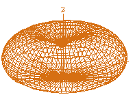
A vertical tends to be more noisy than a horizontal wire, and 80 meters is a noisy band during the day. The narrow bandwidth of this antenna will reduce "out of band" noise, and the actual performance is quite acceptable. The pattern from the antenna would suggest that it is a good DX antenna and my experience would confirm that it does well if you can find long skip conditions. My best DX on 80 with the inverted L was the East coast from Oregon (pretty easy on winter nights) and Hawaii on a 160 meter version. My only reason to operate 80 meters is to contact hams on the west coast; stations I might not run into when operating the higher bands. With the solar cycle waning now, I would not want to be without a wire on 80 meters! 
| |


