 Page 1 (Click to enlarge)
So far I have the circuit designed. I would love some feedback on the approach before I go to all the trouble of making a circuit board. It is inspired by the discussion of the deluxe thermometer at Hart Scientific
|
Page 1 (Click to enlarge)
|
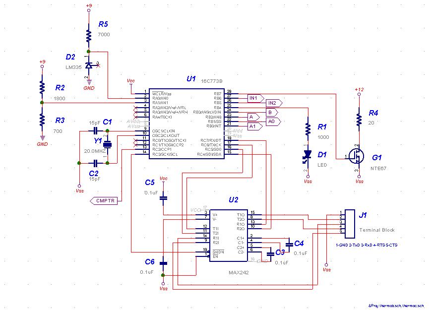
Page 1 includes the microprocessor, a PIC 16C773. Features that make the 16C773 nice for this application include a 12-bit analog to digital converter, a flexible and accurate set of timers and an integrated RS-232 interface.
The PIC 16C773 A/D converter is used to measure the battery voltage (R2 and R3) and the temperature of the circuit board (R5 and D2). D2, a National LM335, acts like a zener that varies at 10mV/degree C. I plan to use the temperature measurement to allow the firmware to turn R4 on and off to heat the analog circuitry to around 100 degrees F. The idea is to lessen the effect of external temperature on the circuit. R4 is a heat rope that will be wound around the analog circuitry compartment to form an oven. The 12-volt power supply runs only R4 and can be left unplugged to make the unit more portable.
U2 is the serial interface driver circuit. It's a flexible circuit that has been configured here to allow RTS/CTS flow control D1 is an LED used to indicate that power is on and that RS-232 data is being sent and received. It is handy when trying to build cables to interface a computer to the unit.
 Page 2 (Click to enlarge)
|
Page 2 includes a 5-volt power regulator and a 2.5-volt reference, the LM4140.
The circuit uses three 9-volt batteries for power. Yeah, I know, but I wanted the analog circuitry to have a power supply that is completely separate from the digital noise. The first 9-volt battery is used only to power the 5-volt circuits via S1. The other two batteries are used for +- 9-volts to run the op-amps on page 3.
 Page 3 (Click to enlarge)
|
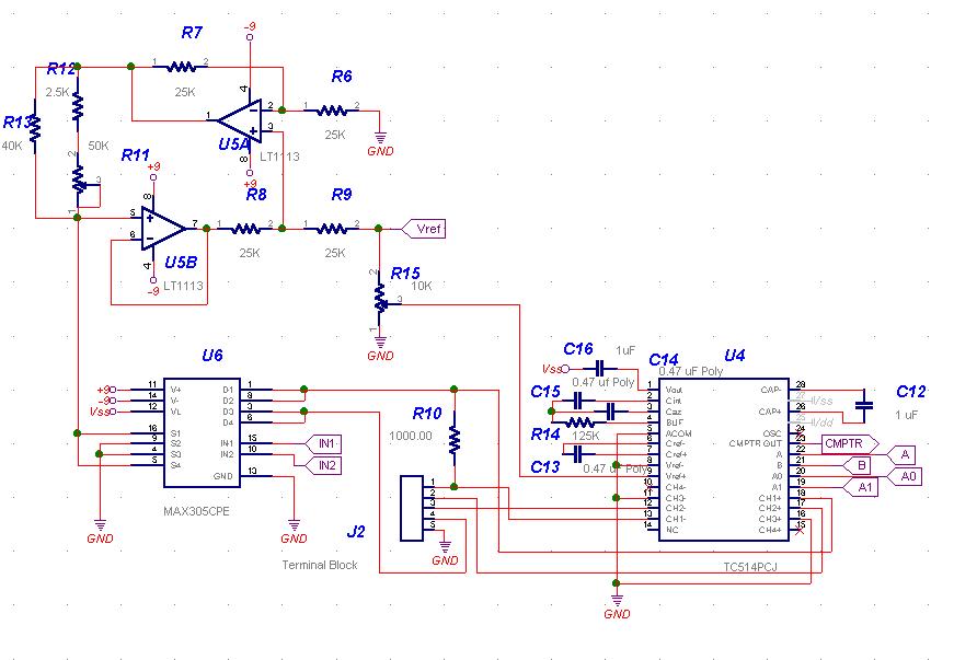
Page 3 contains the analog circuitry. Starting on the top left, U5A and U5B are a pair of low noise op-amps configured as a precision, constant current source. The current is controlled via the resistor network R11, R12 and R13. The resistance can vary from about 2.5K to about 25K ohms. The circuit supplies 1 MA (2.5K Ohms /2.5 Volts) to 10 uA (25K Ohms /2.5 Volts). See this app note for a full discussion of the current source.
U6 is an analog switch used to switch the current so that it can be directed either direction through the 1K reference resistor, R10 and the platinum thermometer, connected to J2. The 1K resistor is an exotic, 0.01% Vishay foil resistor. It was chosen because the circuit's performance hinges on it precision and stability.
U4 is a TC514 from Microchip. It is a highly integrated 16-bit dual-slope A/D converter with a 4 input differential analog multiplexer. The PIC processor controls it via the digital inputs A and B. The multiplexer is controlled via A0 and A1. The output of the conversion process is a digital signal on CMPTR. The PIC monitors CMPTR as an input line and counts the time to integrate the signal on C15.