VATS and PASSKey Vehicle Anti-Theft
Systems
General Information
The Pass-Key, Pass-Key II, or VATS, as it's called in earlier GM
vehicles, uses a resistor mounted in the key blank to confirm that the
correct ignition key is being used to start the engine. Many
people call the resistor pellet a "chip" due to the common
misconception that it is some sophisticated digital circuit to identify
the key to the car. Not quite. It is not a “chip” of
silicon as is customarily used for integrated circuits, but merely a
block of carbon appropriately sized to have a desired electrical
resistance.
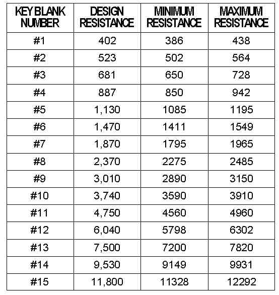
GM mixed about fifteen different resistance values in their pinning
codes to add another factor to make vehicle theft more difficult.
The resistor blocks are staked into the key bodies, just between the
key bow and pinning cuts. If you desire a replacement key for a
VATS equipped vehicle, they are available through almost any GM
dealership. These are usually priced about 3 times higher than
the same key can be purchased at any reputable locksmith. If you
have a VOM (multimeter), you can measure the resistance of the pellet
and inform the locksmith of the blank you will need, or simply allow
them to test and match it.
Vats Key Codes & Resistances
(Ordered in KEY BLANK numbers from 1
to 15, Resistances in Ohms)
System Operation
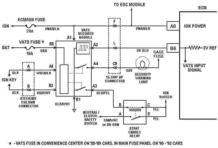
When the system is operating in normal mode, the VATS decoder reads the
correct resistance during cranking. The module grounds the Start
Enable Relay coil. When the start enable relay contacts close,
voltage is allowed to the "S" terminal of the starter. The VATS
module also sends an enable signal to the ECM. This signal allows the
ECM to operate the fuel injectors during cranking. The SECURITY
light will also illuminate for approximately five seconds, then turn
off and remain off.
If an incorrect or no key resistance is read by the VATS decoder
module, the module will shut down the start enable and ECM signal
outputs for 4 minutes. The SECURITY light will flash during the
cranking attempt, and will remain on during the 4-minute
duration. Even if the correct resistance is read within that 4
minute duration, the VATS module will not operate the relay or signal
the ECM..An error code.53 will also be set if the proper signal is not
being received on CKT 229 by the ECM when the ignition is turned
ON.
If an incorrect resistance is detected by the VATS module after the
engine is running, the VATS module will allow the vehicle to be
restarted, even with an existing failure. The SECURITY lamp will remain
on to warn the driver that a VATS system fault is present. However,
this also means that the car can be started w/o a correct key
resistance, and is therefore vulnerable to theft. An error code.53 will
also be set by the ECM in this mode.
NOTE -This error code does not store
in VRAM memory, but is only present while the condition exists, and is
useful as a diagnostic tool in troubleshooting VATS systems.
To signal the ECM that a correct key resistance is sensed, the VATS and
PASSKey systems use a grounding square wave at a 30Hz rate. The VATS
module uses an NPN output transistor to pull down (ground) the 5 VDC
reference voltage presented by the ECM on terminal B6. The reference
signal must be alternately grounded and allowed to be pulled up by the
ECM internal resistor 30 times per second (30 Hz) and at a 50% duty
cycle. This method was selected to prevent the simple powering or
grounding of an ECM input to enable the fuel injectors. The
signal is only needed during cranking to enable the injectors.
Once the engine is running, the VATS signal can be removed and the
engine will continue to operate normally, although with the SECURITY
warning lamp on.
The PASSkey-II signal is a similar square-wave pulsed-ground, but at a
50Hz rate, 50% duty cycle.
Circuit Description
The system uses two leaf contacts in the outer end of the ignition lock
cylinder to connect to the resistor pellet embedded into the key blank
just below the bow. The wiring from these leaf contacts travels down
along the steering column wire harness, where it connects to the
vehicle harness at the base of the column. Usually, the VATS
wiring in the column is in an orange covered cable, sometimes black,
and has a lone two-wire connector (no other circuits in the
cable). The circuit continues from there to the VATS decoder
module via purple/white and white/black wires. The VATS decoder
module is located beneath the dash in the LH foot well, near the kick
panel.
The VATS decoder module has sixteen connector pins, but uses only eight
wires:
An orange wire from B+ for a constant 12VDC to pin
B8;
A purple/white and a white/black wire from the key
contacts,
A pink/black wire from the ECM/IGN power fuse to pin
A1;
A dark blue wire connected from pin A2 to the ECM
pin B6;
A gray wire to the “SECURITY” lamp in the instrument
panel from pin A4;
A yellow/black wire to the start enable relay
operating coil ay pin A3;
And a ground on a black/white wire at pin B1.
NOTES
-
Circuit 229 used a dark blue wire in 1988-90, and the circuit passes
through the C207 connector between the ECM and dash harness.
Earlier
VATS systems may have used a white wire for this circuit, but the
connection to the ECM on pin B6 and schematic is the same.
Some systems may use two white wires
between the lock cylinder and VATS decoder module.
The key resistance wires may be encased
in a black covering, or an orange covering.
Diagnosis & Test Procedures
If the engine WILL CRANK and a code 53 is displayed, that indicates
that the VATS decoder module has detected a correct key resistance, and
has grounded the relay coil negative wire for the start enable relay,
but that the ECM is not receiving the VATS signal from the
module. That can be caused by either a failure of the VATS module
output which generates the signal, or Circuit 229 between the VATS
module and ECM is open or shorted to ground.
If the engine DOES NOT crank and a code 53 is displayed, that indicates
that the VATS decoder module has not detected the correct key
resistance, and therefore has not enabled the start enable relay, or
there is an incorrect starting procedure.
It is common for the leaf contacts and/or the resistor pellet on the
key bow to become contaminated to the point where the VATS decoder
module cannot correctly sense the pellet resistance, or cannot sense
any resistance at all. This would usually cause a no crank/no
start situation. Cleaning the key pellet and leaf contacts can
frequently restore system operation. Because of the risk of
contamination and other reasons, NO liquid lubricants should ever be
used on the ignition lock cylinder. The generally accepted
lubricant for ANY lock cylinder, whether a plate or pin type mechanism,
is powdered graphite ONLY. This especially applies to VATS
ignition lock cylinders.
It is also common for the two wires from the ignition lock cylinder
contacts to break due to the necessary flexing which occurs every time
the ignition lock is moved. This can usually be diagnosed by
measuring key pellet resistance at the VATS module or at the connector
at the base of the steering column.
There is a small two-wire connector in the upper bowl of the steering
column which can become damaged or disconnected as well, since
clearance between moving parts in the upper column bowl are
minimal.
The connector at the base of the steering column can fail if subjected
to stress, moisture, or movement if the lower bolster trim is not
in place.
The connector at the VATS decoder module is generally reliable, and the
connection at the start enable relay is also relatively safe from
interference and reliable. However, all connections should be
checked when diagnosing the system since any connection can fail or add
resistance to the circuits. The start enable relay itself is a
mechanical device, and can fail after prolonged use.
The following diagrams and charts may be useful in understanding and
diagnosing the system:


