|
|
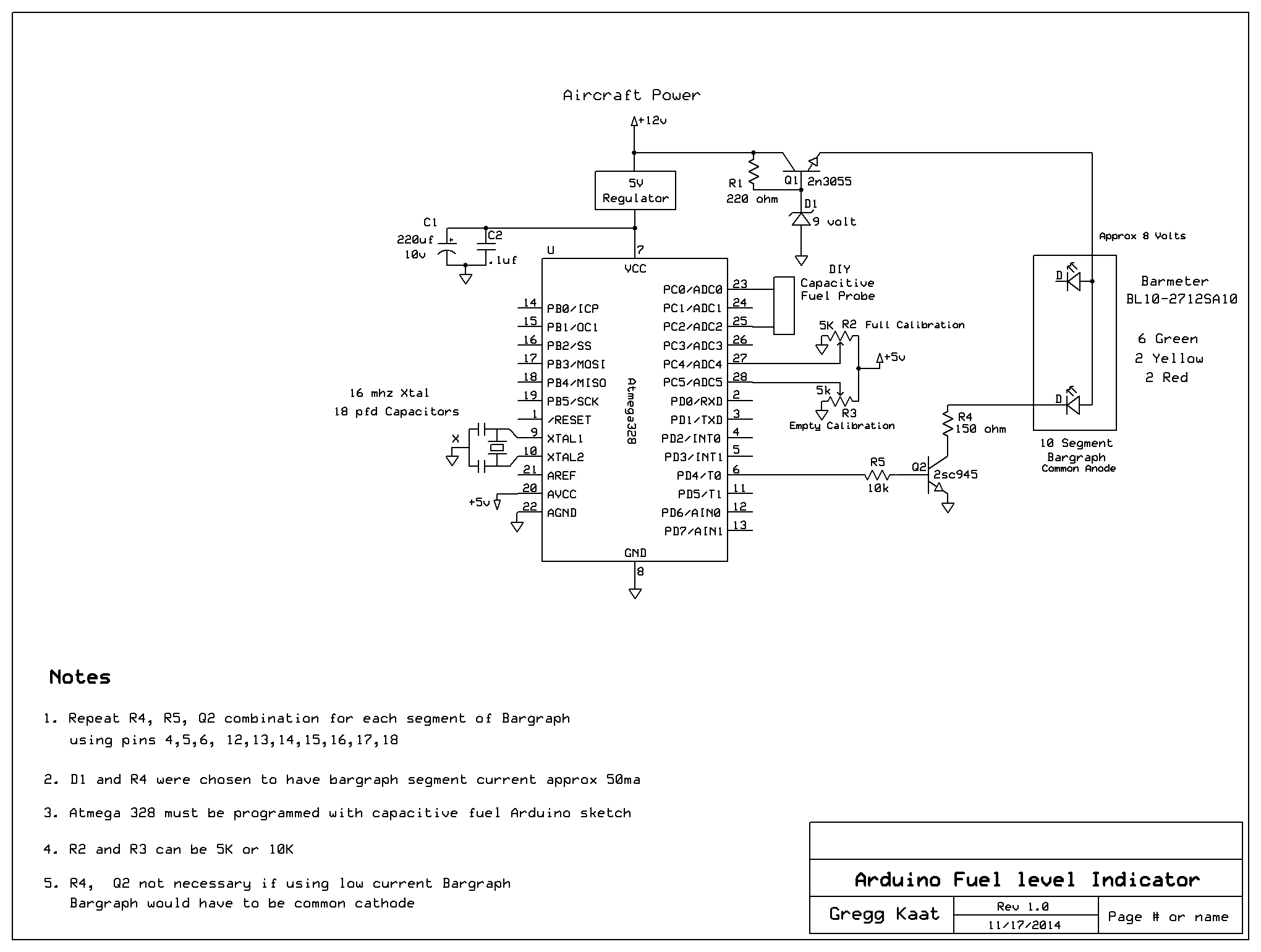
| This circuit reads a capacitive type probe and requires knowledge of the Arduino platform for programming microcontrollers. The software is free and the hardware can be obtained cheaply on EBay. Here
is an example. The microcontroller is an Atmega328 which is cheap and
easily obtained. To save some trouble, you can buy them with the
Arduino bootloader already installed. The bootloader is a subroutine
that lets the chip accept the arduino programming from your
developement board. You can also buy the chips at a cheaper cost and
load the bootloader yourself but it can sometimes be troublesome to get
it to work. I'm retired and have the time to fuss with it so I go ahead
and do that. There is definately a learning curve here but the Arduino
software has a lot of examples. There are a ton of projects on the net
as well. The nice part is it's open source so anybody can use it.
I take bits and pieces from various projects and combine them into
projects of my own. I'm not a programmer by any means but can cut ,
copy and paste just fine. Once you have played with the code long
enough it becomes easier finding your errors if your code is not
working the way you want. In this circuit the microcontroller does all
the thinking and the rest of the components are just for handling the
large amounts of current for the display. The microcontroller can only
source a total of 200ma and this circuit as drawn is drawing about
500ma. The regulator for the display requires a small heatsink. I use
old chassis from various electronic devices for a lot of free parts.
The 2sc945 transistors are found in old tv chassis and capable of
100ma. We are shooting for about 50ma per segment so they are
adequate. You could substitute whatever you want for those. Just make
sure they are good for 100ma or better. The transistors are merely
acting as switches turning the segments on and off as needed. Collector
resistors should be 1/2 watt. They are going to get warm. My DIY
probe is connected directly to the microcontroller. The capacitance
changes as fuel rises or falls within the probe. The microcontroller
reads the capacitance directly from the probe and does not need to
convert anything. It then decides how many segments to light.
Calibration for empty and full are determined by reading some pots.
These chips can be reprogrammed at any time. So if my table of values
is not working for your probe, it will be up to you to change them and
reprogram. The mapped values in the middle of the code is
the spot you are looking to change if necessary. You could do a serial
read of your probe on a computer before installing it and see if it
falls withing range. Look at my You Tube video for this. The Bargraph display can be found Here.
The Arduino code for this project follows. Just copy and paste into
your Arduino IDE software and upload into your chip and you should be
ready to go. const int OUT_PIN = A2; const int IN_PIN = A0; //Capacitance between IN_PIN and Ground //Stray capacitance is always present. Extra capacitance can be added to //allow higher capacitance to be measured. const float IN_STRAY_CAP_TO_GND = 24.48; //initially this was 30.00 const float IN_EXTRA_CAP_TO_GND = 0.0; const float IN_CAP_TO_GND = IN_STRAY_CAP_TO_GND + IN_EXTRA_CAP_TO_GND; const int MAX_ADC_VALUE = 1023; //averaging setup const int numReadings = 10; int readings[numReadings]; // the readings from the analog input int index = 0; // the index of the current reading int total = 0; // the running total int average = 0; // the average //Bargraph setup const int ledCount = 10; // the number of LEDs in the bar graph const int led1 = 2; const int led2 = 3; int ledPins[] = { led1, led2, 4, 6, 7,8,9,10,11, 12 }; // an array of pin numbers to which LEDs are attached void setup() { // initialize all the readings to 0: for (int thisReading = 0; thisReading < numReadings; thisReading++) readings[thisReading] = 0; pinMode(OUT_PIN, OUTPUT); //digitalWrite(OUT_PIN, LOW); //This is the default state for outputs pinMode(IN_PIN, OUTPUT); //digitalWrite(IN_PIN, LOW); // loop over the led pin array and set them all to output: for (int thisLed = 0; thisLed < ledCount; thisLed++) { pinMode(ledPins[thisLed], OUTPUT); } Serial.begin(9600); } void loop() { //Capacitor under test between OUT_PIN and IN_PIN //Rising high edge on OUT_PIN pinMode(IN_PIN, INPUT); digitalWrite(OUT_PIN, HIGH); int val = analogRead(IN_PIN); //Clear everything for next measurement digitalWrite(OUT_PIN, LOW); pinMode(IN_PIN, OUTPUT); //Calculate and print result float capacitance = (float)val * IN_CAP_TO_GND / (float)(MAX_ADC_VALUE - val); int sensorval = capacitance; // subtract the last reading: total= total - readings[index]; // read from the sensor: readings[index] = sensorval; // add the reading to the total: total= total + readings[index]; // advance to the next position in the array: index = index + 1; // if we're at the end of the array... if (index >= numReadings) // ...wrap around to the beginning: index = 0; // calculate the average: average = total / numReadings; // send it to the computer as ASCII digits delay(1); // delay in between reads for stability // read the sensor: int sensorReading = average; //full calibration pot hooks to A4 with rising voltage //empty calibration pot hooks to A5 with falling voltage int MapHi = analogRead(A4); MapHi = map(MapHi, 0, 1023, 160, 200); //map calibration ranges int MapLow = analogRead(A5); //to initial dry capacitive MapLow = map(MapLow, 0, 1023, 10, 40); //measurement of probe // map the result to a range from 0 to the number of LEDs: int ledLevel = map(sensorReading, MapLow, MapHi, 0, ledCount); // loop over the LED array: for (int thisLed = 0; thisLed < ledCount; thisLed++) { // if the array element's index is less than ledLevel, // turn the pin for this element on: if (thisLed < ledLevel) { digitalWrite(ledPins[thisLed], HIGH); } // turn off all pins higher than the ledLevel: else { digitalWrite(ledPins[thisLed], LOW); } if (digitalRead(led1) == 1 && digitalRead(led2) == 0) { digitalWrite (led1, HIGH); //Blink bottom led if it's delay (200); //the only one lit digitalWrite (led1, LOW); delay (200); } } Serial.print("Capacitance Value = "); Serial.print(average); Serial.print(" pF "); Serial.print(" Calibration low = "); Serial.print(MapLow); Serial.print(" pF "); Serial.print(" Calibration High = "); Serial.print(MapHi); Serial.println(" pF "); while (millis() % 500 != 0) ; } Home Page |