|
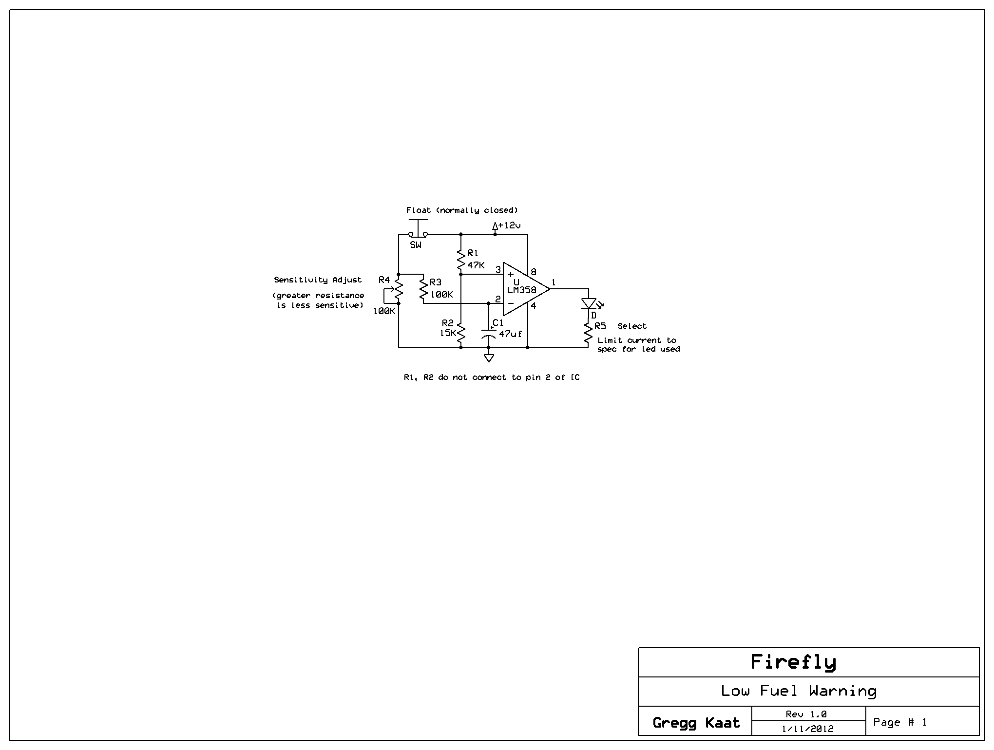
| This is the smallest
and perhaps the easiest to understand of my circuits. The op amp is
used as a comparator. A reference voltage is set on pin 3 with the R1,
R2 voltage divider. The sample voltage is comprised of a float switch
which I have mounted in my tank at the 1 Gallon
mark and the remaining components. C1, R3 and R4 form an RC time
constant circuit which acts to compensate for fuel sloshing in the
tank. As long as the float switch is closed, the capacitor is allowed
to charge to its full amount and the comparator will not see enough
difference between the inputs to trip and the light remains off. As
soon as the float switch opens, the capacitor begins to discharge at a
rate set by R4. If the switch is bouncing on and off due to slosh, the
capacitors charge is increased or decreased at the rate of the switch
making and breaking. The sensitivity should be set so that the switch has to be open for say 45 seconds to a minute before the light turns on thus keeping the light from randomly turning on and off due to slosh. This circuit is easy to Breadboard and simulate so would be a good first start for anybody new to electronics. I should mention that I ended up with a fuel leak where the switch was mounted on my tank. I'm not sure if I didn't have it mounted tight enough or the gasket failed. just to be sure, I refitted the float switch with a couple of DIY gaskets inside and out made from some poly material from a Harbor freight siphon line I had lying around. It has not leaked since and has a couple of years time on it now. Home Page |