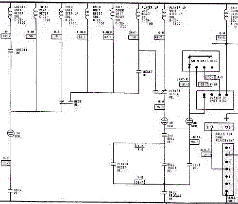
Although a pinball machine and its schematic can look very intimidating, the circuitry consists mostly of simple circuits. It is quite easy to trace a circuit from the power line to the return line. There are numerous parallel circuits that connect to these two lines. Between these two lines most of the circuits are simple with only switches and coils. Some can become quite complicated however. In the section of schematic shown below you can easily determine what switches must be on in order for certain coils to operate. The coils may power a relay or it could power a playfield component such as flippers, bumpers, etc.

As you can see there are various combinations of series and parallel circuits. Each path of the circuit from the power line along the top to the return line along the bottom must have a potential (voltage) drop equal to that coming from the transformer. Notice that the only load in any one path is the coil (or light bulbs on the other secondary's circuits).
The easiest way to check that a coil SHOULD work would be with a continuity test. If continuity is not established, even though all switches may be on, then there's a break in the circuit somewhere. The causes could be broken wires, oxidized contacts on the switches, etc.
Once continuity is established a simple way to troubleshoot a non-functioning coil is to perform a zero ohms test. A coil must have sufficient current passing through it in order to perform its task. If there's resistance in another part of the circuit the coil may not be getting enough current to function. The amount of resistance in the wires and switches should be near zero. Using a multimeter and connecting to the return line, one can proceed along the circuit, activating switches along the way. If all switches are on between the coil and the return line there should be nearly zero resistance. Anything over 1/4 ohm would be suspect. Infinite resistance would indicate a break in the circuit somewhere.
Another troubleshooting method that works to isolate problem areas when the circuit is working is to perform a voltage drop test. Continuity must be established before this test can be performed. This test utilizes Ohm's Law to determine where a problem exists. Since V = IR then anywhere there is resistance there will be a volltage drop (or potential difference) across that part of the circuit. The only drop in any of these branches ought to be just in the coil. Place one side of the voltmeter on the power side of the coil. Then place the other voltmeter lead on the other side of the coil. If the voltage is close to that coming off the transformer, then there is no unwanted resistance in any other part of the circuit. If the voltage is lower though, then proceed along the circuit and watch the potential difference. Once you test beyond the trouble switch you will see a rise in the potential difference, and you have just located the problem.