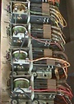
In addition to lots of switches, light bulbs and wires, the remaining components of the pinball circuitry is just a bunch of solenoids and relays. In each case, wire of various guages is wound around a bobbin.

A section of relays from a Bally game

A relay is a small coil that pulls in, which activates a number of switches. So one switch turns on the relay coil, which in turn activates a number of other (normally open or normally closed) switches (from one to many). So you can have one switch (like a playfield switch) turn on a relay, which will then turns on (or turns off) many switches, which could control several game features.

AC relays have a copper "slug" center surrounded by an iron center. AC coils have a coil stop made with these same materials. This material creates a small magnet. This holds the magnetic field of the coil as the AC (alternating current) moves through zero volts (remember, AC volatage alternates from a positive voltage, to zero volts, to a negative voltage, and back to zero, then to positive voltage, and so on). An AC relay or AC coil stop will work in a DC circuit, but a DC relay or DC coil stop won't work in an AC circuit.

Some relays are designed so they may stay on for long periods of time. They can stay on without burning because they are low power, and consume limited juice. "Hold Relays" are designed to stay on sometimes the entire time the game is turned on. Hold relays are used on the coin mechanisms and for the game power hold (part of the tilt circuit).
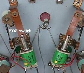
 

Flipper solenoids.

Solenoids are bigger versions of relay coils. They are much larger, and consume much more power. Hence they can only be on for very short periods of time (otherwise they will smoke and burn). Solenoids have a center hole through which a plunger travels until it hits a "coil stop". When a solenoid is switched on, it pulls this plunger down inside the solenoid coil. An example of this is the flipper coil. Flipper Coils are a unique type of solenoid. This coil is actually two coils in one package. One part of the coil is the high-powered side. This uses large diameter wire, with a limited number of turns (low resistance). Since there is low resistance, the power can travel quickly and easily through these windings. This part of the coil gives the flipper its initial power to kick the ball.

The second part of the flipper coil is the low powered side. This acts much like a hold relay; lots of turns of thin wire with high resistance. This part of the flipper coil is normally shorted out and bypassed by a normally closed end of stroke (EOS) switch.

It works like this: When the player presses the flipper button, the high-powered side of the flipper coil is activated, and the low-powered side of the coil is bypassed. The high-powered side of the coil moves the flipper plunger through it's stroke. As the flipper reaches it's end-of-stoke (EOS), the flipper pawl opens the normally closed EOS switch (which has shorted out the low-power side of the flipper coil). When this switch is opened at the end of the flipper's travel, the electricity passes through both the high powered and low-powered sides of the flipper coil in series (one after the other). The combination of these two coils together (with a combined resistance of the two coils) consumes less power. This allows the player to hold in the flipper button without burning the flipper coil. If the high-powered side of the coil was activated alone for more than a few seconds by itself, the coil would get hot, smoke, smell, and burn.