You can click on any of the images to see a bigger version.
This project shows how to find ants with a camera, track them and zap them with a laser. When I planned this project I considered buying a high-powered laser on EBay but the thought of my grandkids wearing safety glasses made me reconsider. No ants have been fried: the laser is just a 5mw laser diode like the ones in low-power laser pointers. Here are the initial questions and the current answers:
| Is it possible to find moving ants? | Yes, image background subtraction works. |
| Is it possible to recognize ants with a camera? | Yes, a neural network can handle it easily. |
| How about tracking them? | Yes. |
| Could I hit something that small with a laser? | Sometimes. |
| Could I move the lasers fast enough? | Easily. |
| Can we do all of this at camera frame rates? | Yes, for reasonable numbers of ants. |
|
You can click on any of the images to see a bigger version. |
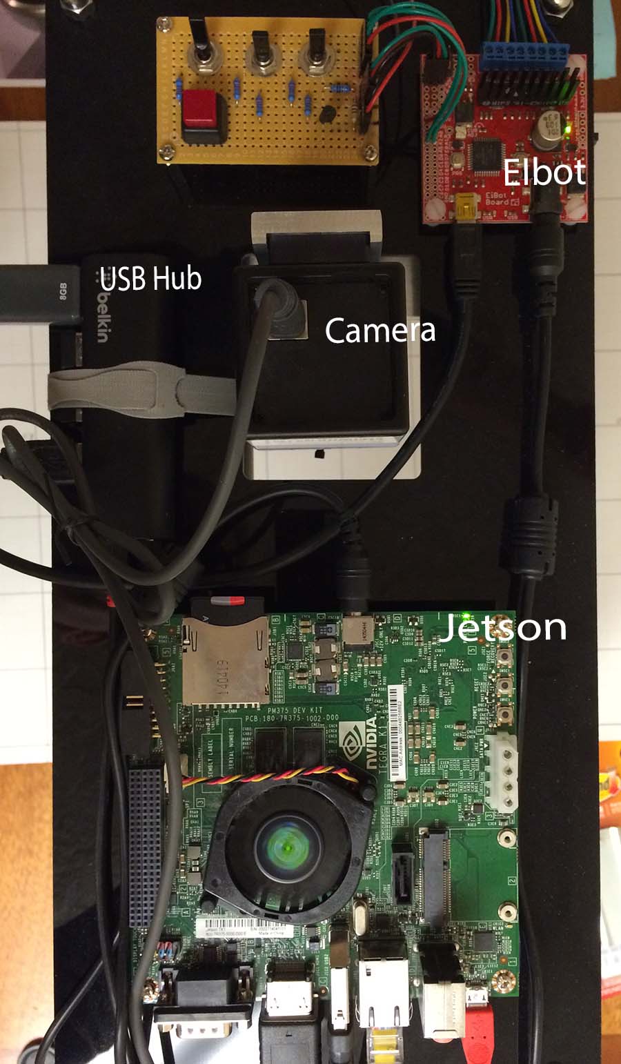 |
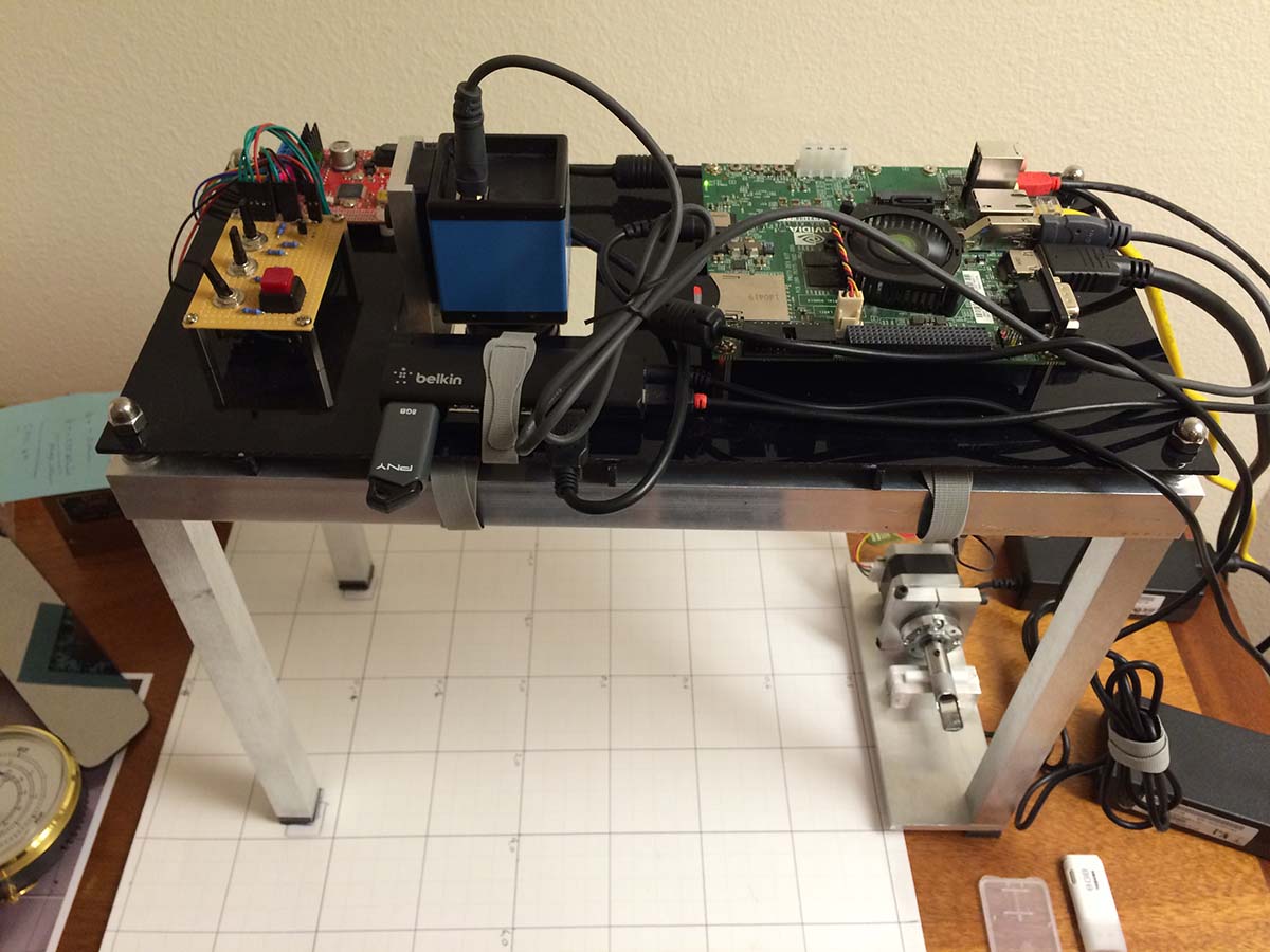
In the picture at the left you can see the top of the unit. I bought the EIbotBoard from SparkFun but it looks like they have discontinued it. I did find a board that looks equivalent at Evil Mad Scientist The board is perfect for this project. It will simultaneously drive two steppers at about an amp apiece. It is powered by 12 volts and plugs into a USB port. It looks like an async serial port to Linux.
The board on the top left is a debug aid. The red button gracefully resets the unit. The toggle switch on the left turns the laser on and off manually. Normally the laser is under computer control. The other two switches can be used to drive the x and y stepper motors. The switches and the laser are connected to pins on the EIBotBoard and can be read (the switches) or written (the laser) via serial commands over the USB.
 End view |
On the left of the picture is a powered USB hub. It is connected to the other USB port on the Jetson and to a wireless keyboard, a wireless mouse, the EIbotBoard and usually a thumb drive for backup.
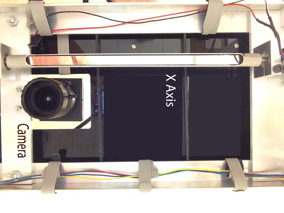 Looking up at the X axis |
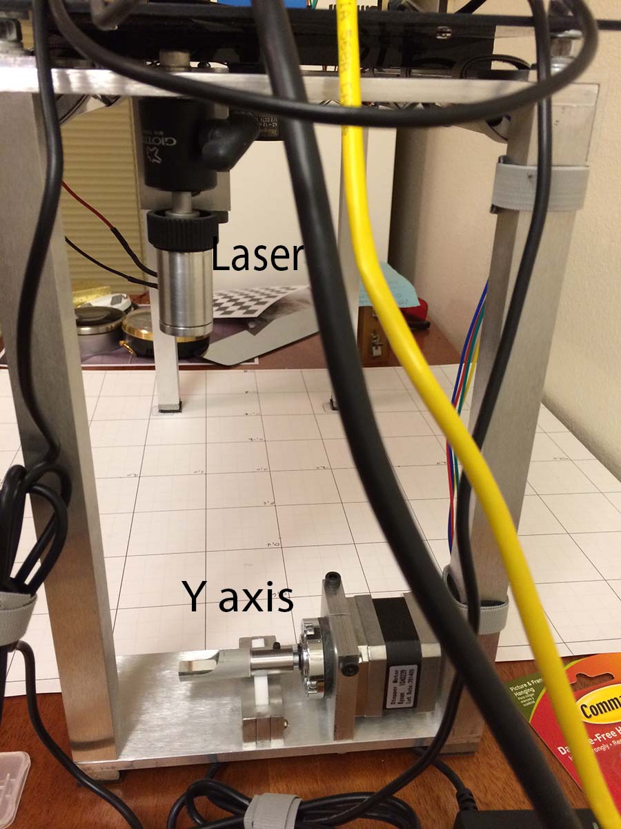
The laser is mounted in the small aluminum housing in the photo on the far right, attached with a camera swivel mounting to the frame. The Y axis stepper motor and the small mirror on the end of its shaft can be seen at the bottom of the photo. The X axis is the long thin mirror mounted under the circuit boards.
Light bounces from the laser to the Y axis to the X axis to the ant. The 200 steps per revolution motors have 5.2:1 reduction planetary gearheads. The EIBotBoard runs 16x microstepping so we have roughly millimeter resolution over most of the field of view of the camera. The gearheads add backlash that is hard to model; that seems to be the main source of errors positioning the laser.
Here are the mirrors in action:
Once a frame is captured from the camera it is passed directly to the GPU. The GPU runs a VIBE background subtraction to isolate pixels that have changed. That background subtraction returns a foreground mask with pixels that have changed set to 255, the max value for the 8 bit pixels. Since a lighting change can blow out the background subtraction, the next step the GPU does is to count the number of pixels in the foreground mask. The background subtraction algorithm is reset if there are more than 5000 pixels lit up. The GPU passes the foreground mask back to the CPU if there are fewer than 5000 pixels set.
The CPU produces a list of isolated blobs of pixels from the foreground mask. The camera image for each blob is passed to Caffe for classification. Each blob gets a score that says how likely it is to be an ant. Blobs that may be ants are passed to a class that maintains the current list of ants. Blobs that are in a position near the predicted position for the ant are "claimed" by the ant. Blobs that look like ants but don't match up with a current ant cause a new ant to be created. Ants that haven't matched up with a blob for a while are eventually removed.
The "best" ant is picked based on the total score and the distance from current laser position. The time to move the laser to the ant is estimated, and then the position of the ant at that time is estimated to provide a new estimated position. Then the motors are started. Once the motors finish the laser is fired for one frame time. Ant positions are tracked while the motors move.
The trained model was used as a classifier in the main project. It takes about 8 ms to classify an image. This is OK for a few ants. Given the simple nature of the images, network tuning should reduce these times. The nice thing about using a neural net is that new setups can be added to the set of images and the network can be retrained. Over time this will produce a general model.
The mapping from C1 to C2 involves undistoring the image from the camera and converting units from
pixels to inches.
Fun with Mathematica gave me the equations that map the
camera's distorted view
of the world into a rectangular
grid. I used the stock
6th order equation
used by OpenCV but there was no point in undistorting the full image. I really only need to map the location of the
single point in C1 at the center of the selected ant to the point on C2. I ended up running a least squares
fit in Mathematica to find the coefficients:
{K1 -> 0.0010958, K2 -> 0.00021057, K3 -> -5.575*10^-6,
This must be redone for each new lens. I used an iterative
process to find an accurate focal length for the lens.
P1 -> -0.00299204, P2 -> 0.000119739, P3 -> -0.0227986}}
The mapping from C2 to C3 involves a 180 degree rotation about the C2 center and calculating the rotation angles for the mirrors. Mathematica also helped with solving the equations for the mirror angles given an x and y coordinate on the C3 z = 0 plane.
Contact me at r.bond@frontier.com for questions or comments.