Stepper Motor Controller
Overview:
This project is a dual stepper motor controller using a PIC processor. The
design controls a pair of bipolar stepper motors in microstep mode. The
software uses the steppers to control the RA and DEC axes on a German
Equatorial mount. The motors drive a 15:1 Bayside gear reduction system.
The Bayside drives a 359 tooth worm gear.
Distribtion:
Everything's packaged in a zip file.
Schematics:
I use Ivex's CAD tools. See their
homepage for the tools.
I converted the pages to jpegs so you can get a feel for the design.
You will want to download the zip files to get the real things.
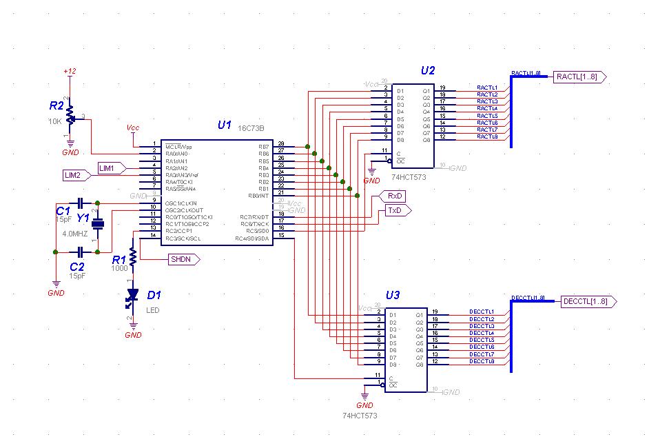
PIC, latches: page 1
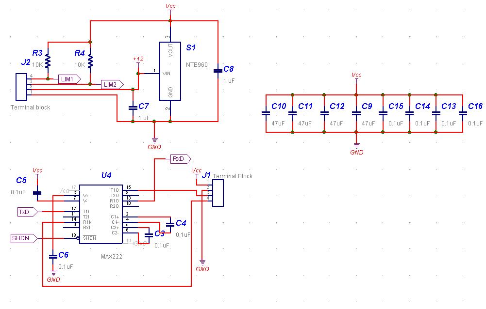
Power, RS232 Driver, Misc: page 2
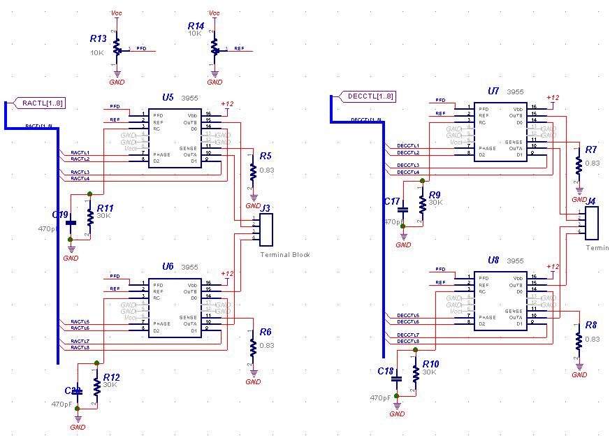
H Bridges: page 3
Palm Basic Software:
I use my Palm 3xe as a paddle to control the mount. The software for the
Palm is written in
Hot Paw Basic.
The screen is formatted with 4 buttons. When the buttons are pressed the
program sends commands via the serial line to the mount. I use a standard
Palm serial cable. The Basic program
is in the distribution. Any computer that can communicate over a serial
line at 9600 baud could be used to control the steppers. This works OK
but tends to burn through batteries pretty quickly since it takes lots
of power to run the serial line and the Palm's back light.
PIC Code:
The software for the PIC is all in assembler using Microchip's
mplab
General Strategy:
The software implements a command loop that monitors the
RS232 port for characters in polled mode.
The port is set up at 9600 baud, 8 bits, no parity
Characters are echoed and buffered to a full line terminated by a CR.
The line is parsed and executed. All motor commands are kicked
off but the timing is handled in interrupt commnands.
Memory layout:
The first 0x800 is all interrupt code and interrupt support routines.
The second 0x800 is all user code and user level support routines.
A slow, goofy macro package is used to implement a user level stack
in the 2nd bank of registers. The first bank is used for interrupt
processing. The user level code is restricted to one deep stack
usage to allow the max. speed at interrupt level.
Timers:
Timer 1 is set to be free-running, clocked at 1/4 FOSC = 1MHZ
CCPR1 is used to time RA events
CCPR2 is used to time Dec events
The timer is never shut off; match interrupts are turned on and off
as the drives need attention
Timer 0 is used as a free running clock, clocked at 1MHZ. The prescaler is
set to 256 so that the timer rolls over every 65.536 MS or a little more
than 15 times per second. It is used for gross user level timing of events
such as polling the battery value.
Commands:
Not all of these commands are fully implemented at this time.
Directions "+" advances in terms of RA or Dec, ie, East or North
"-" decrements RA or DEC, ie, West or South. Tracking is inherently movement to the West and so is negative.
Command set
| F[m][dir] [count] |
Full step [count] steps |
| GC |
Gets the count for both axes |
| GB |
Gets the battery voltage |
| M[m][dir] |
Starts an axis slewing |
| Q[m] |
Stop |
| I[m] |
Idle: Quit and turn power off |
| R |
Reset |
| SC[m] [count] |
Sets the saved count for an axis |
| SS[speed] |
Sets speed for next Slew command (both axes) |
| T |
Starts RA tracking |
| U[m][dir] [count] |
Microstep [count] steps |
Abbreviations:
| [count] - signed 32 bit count of full steps |
| [m] can be "R" or "D" and specifies which motor to use |
| [speed] is "T" for Tracking speed |
| "G" for Guide speed |
| "L" for Lunar speed |
| "S" for Solar speed |
| "M" for Medium (8x) speed |
| "F" for Fast (32x) speed |
| [dir] is "+" or "-" |
Contact Information
You can reach me at r.bond@verizon.net
or rgb@ncube.com I prefer that you use the
verizon address for non-business related items.