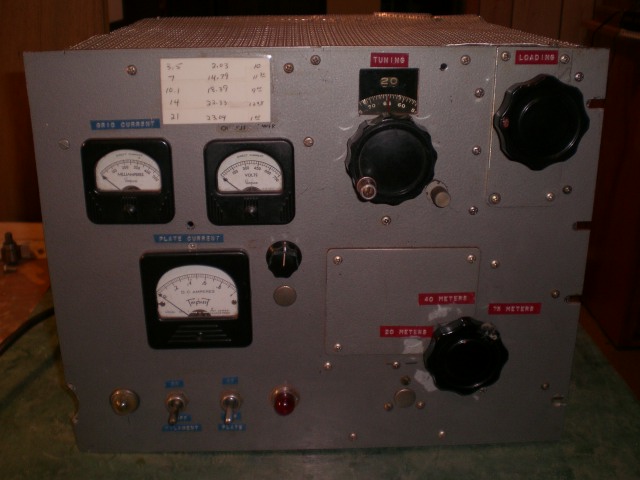
This is what it started out as. More pictures here....As it was!

This is a B&W-850 tank circuit. The coil supports for the right side of the coil were non existent due to age. I made new ones out of Plexiglas and the table saw. Not bad I don't think.
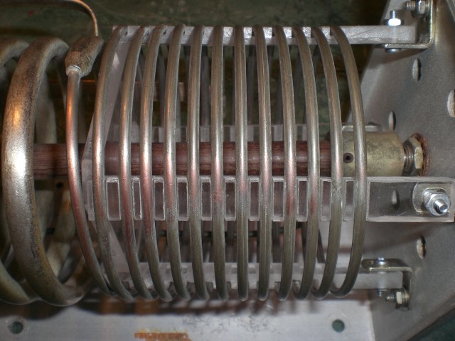
A closer look at my repair job.

One more picture.
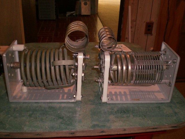
Some folks wanted to know the difference between the 850 and 852 tank coil assemblies. The one on the left is the 852 and is the one that was in the 3-1000 amp when I tore it apart. The one on the right is the 850 which is the one I'm going to use because it has more inductance for 80/75 meters.
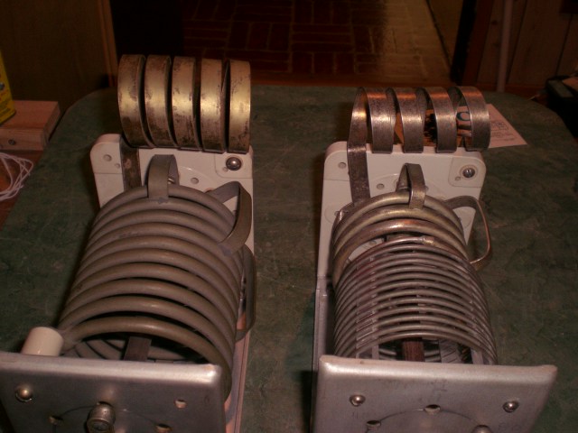
Another picture of the two. B&W-852 on the left and 850 on the right.
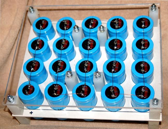
Picture of new capacitor bank for the power supply. 28uf @ 8KV

Another Picture.
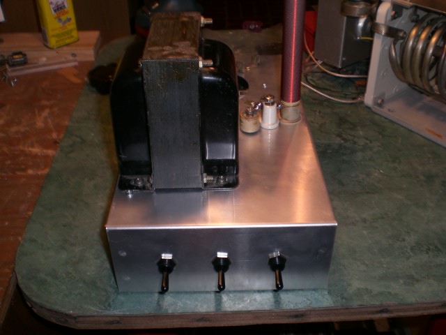
Sub chassis with switches, filament xfmr, & plate rf choke.
Side view showing tube socket and chimney clips.

Rear view of sub chassis. HV connector and power connector on the rear.
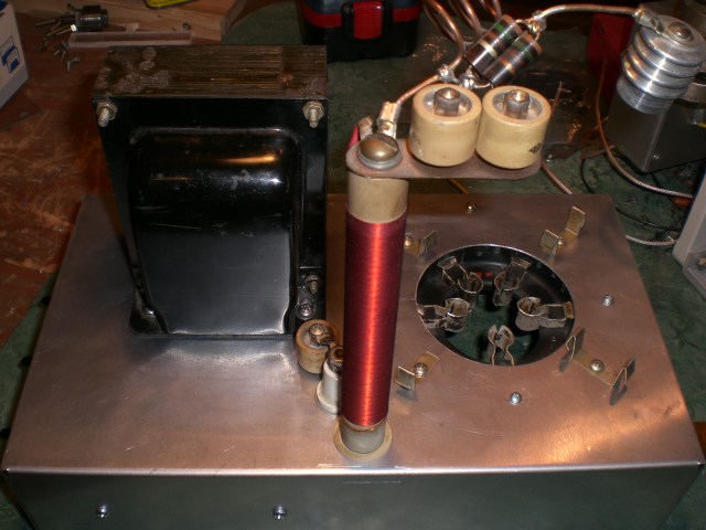
Here's how things will sit on the main chassis yet to be built. On the right is the tank circuit components. The space on the lower right will be used for the additional loading control and capacitors. The TR relay will be mounted to the rear of the same space as well as the input/output connectors.
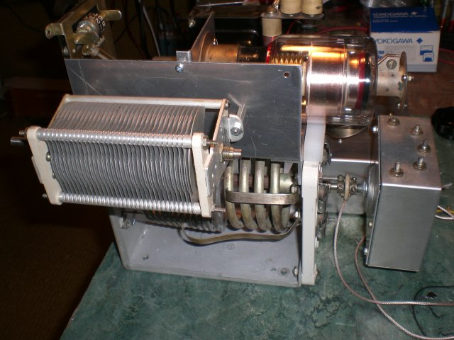
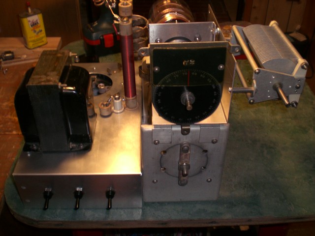
Side view of new tank assembly. Box on the rear is the input tunning.

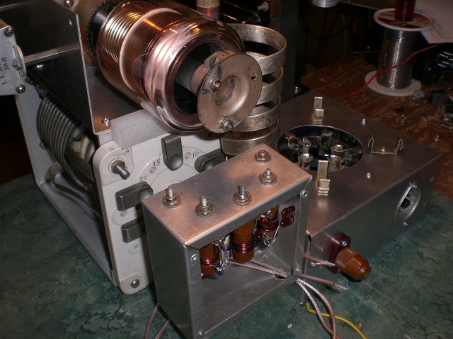
close-up picture showing the coupling of the main band switch for the tank circuit and the input tuning.
Back view.