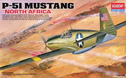
P-51/F6-A Mustang Fighter/Reconnaissance Plane
This was another model I made myself some
promises about before I started:
I was going to brush paint it by hand - no spray cans.
I was going to really work at making seams disappear, rescribe panel lines that got sanded out, and maybe even rescribe all the panel lines before starting.
I was going to focus on detailing the cockpit and splurge on some aftermarket stuff.
I was NOT going to get hung up on every teeny tiny detail (rightttttt).
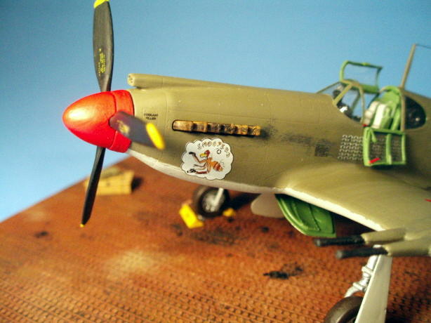
I've always liked the Mustang - it just looks so frickin' fast and predatory, the way a fighter should look. I finished my model as the photo reconnaissance version, in which case it was designated the F6-A, serving with the 111th Tactical Reconnaissance Squadron in the spring of 1943 in Algeria, after the Allies invaded North Africa.
I fudged a little on the decals; I'm not absolutely sure that this exact aircraft had these exact markings at this exact time. But ... it's my model, and I preferred this scheme because it had nose art and the cool eyeball mission symbols on the side. I added the invasion-specific stars with yellow circles and American flags on the tail because it looked so colorful against the olive drab finish, compared to the standard stars and bars the instructions said to use.
The Academy P-51 Mustang 'North Africa' kit (no. 12401) is a nice one, with crisp moldings that needed almost no clean up, nicely recessed panel lines, logical construction and only 49 parts. Plus, they threw in a Willys Jeep and trailer! The only down side is the decals, discussed later.
After a couple of hours of bravely attempting to rescribe all the panel lines deeper, and adding a number of interesting zigzag lines in unusual places, I gave that up and just scribed the spaces between the control surfaces deeper. I did drop the elevators, and removed the flaps so I could reglue them in the landing position. I ended up gluing a piece of half round styrene rod on the open side of the flaps, otherwise there would have been a huge gap to try and hide. And had to add some square styrene tabs to the elevators to recreate the hinge points. They ended up looking pretty good.
This was my first forray into the world of liquid cement; since I wasn't sure I would like it, I got the cheapest bottle of Testors my hobby shop had, instead of some of the more exotic offerings. At the end of the day, though, I was pleasantly surprised - I ended up having to fill fewer seams, the parts by and large stuck together the first time every time, and since it wasn't super glue, I didn't have to worry about sticking my fingers together to the point where surgery would be required to separate them. I decided to use liquid cement to assemble the entire model, with the exception of gluing on the landing gear (superglue, for strength) and the cockpit canopy (Testors clear parts cement).
Once the basic assemblies were finished,
it was on to tackling what I hoped would be the focus of this model - the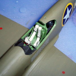 cockpit, or 'office' as some prefer to call it, and the canopy that goes over
it.
cockpit, or 'office' as some prefer to call it, and the canopy that goes over
it.
The Cockpit
I was going to sink some money into aftermarket details to really jazz the cockpit up, but after looking at the price for even a basic set ... scratchbuilding, as I had with the B-25B's cockpit, looked more feasible. I just can't see spending three times what you did on the model to detail an area that is less than 1 cubic inch in size.
Thus deciding, I pored over the cockpit
photos I'd been able to find and decided that a 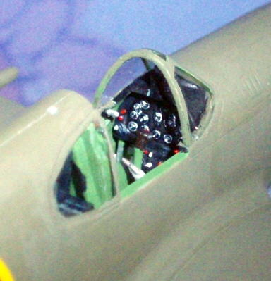 little stretched sprue, some
sheet styrene, wire and masking tape would do the job - stretched sprue for
handles and levers; a chunk of sheet styrene and more stretched sprue for the
missing throttle quadrant; wire for some conduits; and masking tape for my first attempt at seatbelts
and harnesses, with formed wire for the buckles. The first three turned out fine, to my eye, and some careful
painting and drybrushing brought the instrument panel and sidewalls to life.
little stretched sprue, some
sheet styrene, wire and masking tape would do the job - stretched sprue for
handles and levers; a chunk of sheet styrene and more stretched sprue for the
missing throttle quadrant; wire for some conduits; and masking tape for my first attempt at seatbelts
and harnesses, with formed wire for the buckles. The first three turned out fine, to my eye, and some careful
painting and drybrushing brought the instrument panel and sidewalls to life.
The seatbelts were an adventure. I read up on the many different ways to make them and opted for masking tape (cheap!). But all I have is the blue low-tack painters tape. Bummer. Let's paint it flat white and see what happens, shall we? Three thin coats later ... close enough. But dry paint isn't very elastic. It flaked off massively as I tried to bend the thin strips of tape to fit the curves of the bucket seat. And trying to make buckles out of little bits of 24-gauge wire was equally frustrating. Pondered that problem for awhile before hitting on a solution - a single segment of 3-bar railing from one of my 1/700 scale ship kits for the buckles. Paint them aluminum, and ... perfect! A double thickness of plain white 'paper' first aid tape for the harnesses completed things.
The Canopy
This was also my first attempt at using an aftermarket vacuum-formed canopy. The early P-51s had a rather elaborate three-part canopy. I wanted to show it opened up since that would look cool and show off my cockpit efforts (forgetting that it was going to make things a lot harder). By the time it was over, I was glad that Squadron sells you two copies of each canopy. And that I have stock in the Johnson & Johnson Co.*
Vacuformed canopies are prized by model builders because they are thinner, so they look more in scale, and more optically clear than the usual thick plastic parts that come with the kit - you can see more of the cockpit. Dipping the kit-supplied clear parts in Future acrylic floor polish greatly improves their clarity (no one knows why, it just does), but especially on larger-scale models, vacuformed canopies are the rule rather than the exception to show off the maximum amount of cockpit detail.
What I had overlooked was that most vacuformed canopies and cockpit window sets are designed to be used as one piece. Or at the most (for a fighter, say), the one-piece canopy will be separated from the windscreen so it can be posed in the open position. Trying to separate a vacuformed P-51 canopy into its six parts is not a task for the faint of heart. Or the clumsy. Or those whose X-acto knives seem to have an affinity for major arteries when dropped.
Suffice it to say, things didn't go well. I ended up using the kit canopy, after carefully sawing it apart with a razor saw blade and then sanding smooth the rough edges and using thin strips of styrene for the interior cockpit framing.
Painting
Just for grins, I thought I'd list every single paint I used on this tiny thing, more to shake my head in amazement at my own excesses than anything else. All are enamels unless noted:
Flat Black, Testors 1149 - prop blades, cannon barrels, cockpit panels, batteries and radio gear behind seat.
Gloss Black, Testors 1147 - inside of cannon muzzles, few highlights on instrument panel.
Gunmetal, Model Master 1795 - reconnaissance camera.
Dragon Black, Model Master 4400 (Acrylic) - instrument panel highlights, recesses in main wheels.
Flat White, Testors 1168 - instrument panel highlights.
Gloss White, Testors 1145 - instrument panel highlights, rear navigation light.
Flat Gull Gray, Model Master 1730 - all lower surfaces.
Schwarzgrau RLM 66 gray, Model Master 7561 (Acrylic) - interior radiator grilles.
Flat Brown, Testors 1166 - engine exhausts, drybrushed.
Rust, Testors 1185 - engine exhausts, drybrushed.
Rubber, Testors 1183 - tires, tops of batteries behind cockpit.
Burnt Iron, Model Master 1424 (airbrush only, but what the heck) - engine exhausts undercoat.
Flat Red, Testors 1150 - lefthand wingtip navigation lights, prop spinner, gas caps, a few spots on cockpit instruments and handles, throttle quadrant.
Orange, Testors 1127 - underwing recognition light.
Insignia Yellow, Model Master 1708 - prop tips, touch up recognition stripes.
Flat Green, Testors 1171 - righthand wingtip navigation lights, underwing recognition light.
Olive Drab, Model Master 4728 (Acrylic) - all upper surfaces.
Flat Olive, Testors 1165 - fabric control surfaces.
Green Zinc Chromate, Model Master 1734 - cockpit interior, wheel wells, inside of landing gear doors.
Dark Blue, Testors 1111 - underwing recognition light, throttle quadrant handle.
Aluminum, Testors 1181 - landing gear, seat belt/harness hardware, throttle quadrant handle, flap hinge areas, wheels, paint chips in cockpit and on wings.
Chrome Silver, Model Master 1790 - landing gear oleos, inside of landing lights.
Flat Clear, Model Master 2015 - overall final finish.
Now, with that out of the way! Hand painting went surprisingly well. The Model Master acrylics brushed on smoothly with a No. 3 or 5 round sable brush, although I had to lay down two coats to get complete coverage. The enamels had to be thinned a little so they would flow smoothly and not leave streaks or brush marks. I used some 1200 grit sandpaper to smooth down the masking line between the light gray undersides and olive drab uppers, and anywhere the finish looked rough or bumpy. Keep your brushes clean and always paint from the wet edge and you'll do fine.
Decals
As mentioned earlier, I fudged a little on the decals to get a more colorful finished product. Some modelers hate Academy decals with a passion and toss them without a second thought, others have had no problems at all. I'm on a budget so I decided to risk it, and didn't have any problems - at first.
The thing that gets a lot of first-time military modelers in trouble with applying decals is the dreaded silvering - the light-colored, almost glowing ring around a decal after it has dried. This is caused by the paint. For flat paint to look, well, flat, the pigment has to be a lot chunkier, or rougher, to scatter the light beams off in all directions and make the dry paint look dull. If you apply decals over flat paint, the decal film will trap tiny air bubbles, which results in silvering (and generally some bad language about same).
The solution is simple. You can either use gloss paint, which won't work for military models or doesn't come in the colors we need, or you can put something over the flat paint to fill in the little peaks and valleys. I use Future acrylic floor wax. It's cheap, cleans up with water, and almost always dries to a dead level, glossy finish. Below is how I generally apply decals:
Allow base coat of paint to dry thoroughly, at least a day;
Apply Future in areas where decals will go and allow to dry, at least two hours;
Cut out, wet, and apply decals, allow them to dry or apply setting solution to suck them down over panel lines, curves, etc., and allow to dry completely;
Apply a second coat of Future to seal in the decals and protect them. Allow to dry at least two hours;
Apply final clear flat top coat.
I've had absolutely no problems with this method until this model, and it didn't start until three or four days after I'd applied the final enamel clear coat to even out the finish. Some of the decals started silvering. Not around the edges, but in the middle, in odd spots, and in one case in crazy zig-zags. About a quarter of them did this, and at that stage of the game, with the final coat of clear enamel already applied, there was absolutely nothing I could do about it. Several extra coats of flat clear made the silvering less obvious but did not eliminate it. Rats.
Odds and Ends
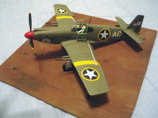
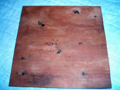
The other big challenge in this project was the display base - I wanted something that would look a little cooler than plain black plastic.
So deciding, I ordered a plastic 1/72 scale PSP base that I could cut down to size to fit my favored Minicraft display case. The Eduard base, no. 7701, nicely represents the pierced steel planking (aka Marsden matting) that the Allies used in WWII to quickly create a runway. Each steel 'plank' was 10 feet long, 15-inches wide and perforated with 87 1-3/4-inch holes; not something I could easily create in that scale!
First I gave it a light coating of Model Master light earth (no. 1954) from a rattle can to simulate the mud/dirt under the PSP. Then I went to town with my Rustall weathering set, really using it intensively for the first time since I bought it. The 'rust' is a wash solution, so you just keep slopping it on until you get the effect you want. At first the finish looked way too uniform, but repeated applications of the 'rust' gave it a more mottled look. The blackwash that you're supposed to use next didn't really bring out much detail, so I drybrushed Testors steel in several areas to simulate wear on the PSP, added some thinned black paint splotches for oil stains, and even sprinkled a little of the 'dust' that comes with the Rustall set on various spots to give it some texture. Here are a few in progress shots:
 |
 |
|
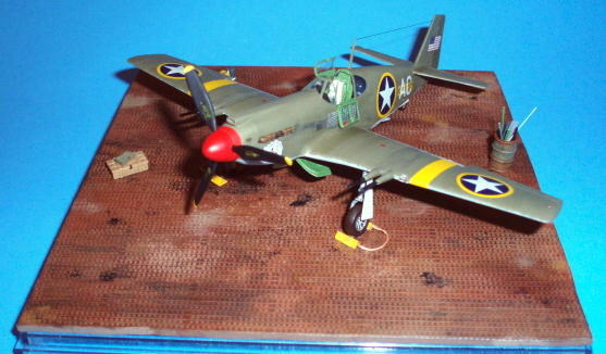
| The pretty much finished Mustang on the about halfway finished PSP base. I couldn't help myself - I had to see if it was going to look as cool as I hoped it would. | A not-very-well lighted shot of the base as I was getting it where I wanted it. Note the individual PSP planks and a few other spots that were drybrushed with steel, the oil spots and stains added with thinned black acrylic paint, and the overall uneven look of rusted steel. |
The completed model. Someday I am going to add a 1/72 pilot or ground crew figure, when I get confident enough about painting people that are only an inch high. And when I can find some that don't look like kid's toys because of lumpy or incomplete molding.
 |
 |
|
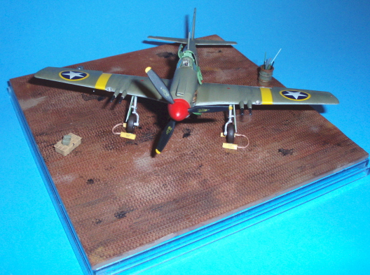
| Finally done! Viewed from the front,
the finished model and PSP display stand depict a F6-A just back from a
photo mission somewhere over North Africa. I added some boxes, jerry
cans and a trash barrel to give things a more life-like appearance.
|
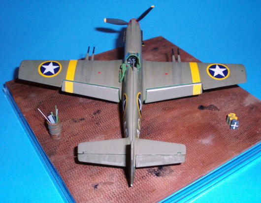
From the rear, the broad yellow identification stripes are even more prominent. The decals weren't long enough and I had to touch them up with Insignia Yellow paint, Model Master No. 1703. | |
 |
 |
|
| One of those little details I love to
work into a model - all Mustangs had a lifting tube that ran the width
of the fuselage, about halfway between the back edge of the wing and the
stabilizer, near the bottom of the fuselage, which I added with a No. 75
drill bit.
|
The cool-looking nose art, and my attempt to produce realistic-looking exhaust stacks. I'm not really happy with how it turned out, and like my attempt at trying to streak exhaust back along the fuselage even less. Oh, well. | |
 |
 |
|
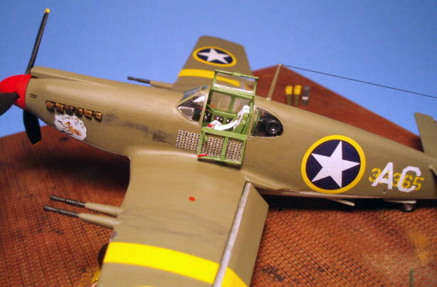
| The finished cockpit (again!), showing
where I had to saw off the top and left side panels. These were then
framed with thin strips of plastic to give them a three-dimensional
appearance. The red lever on the lefthand one is an emergency release
handle, made from stretched sprue.
|
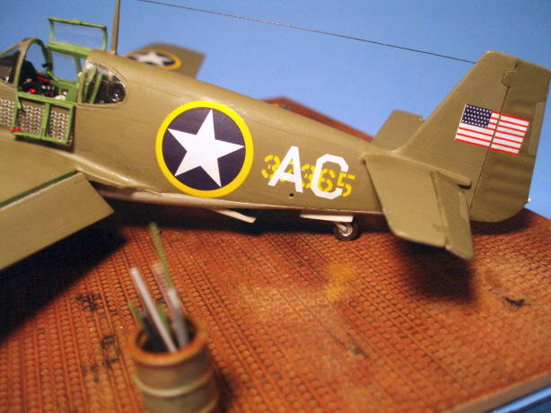
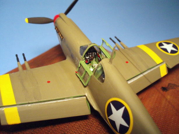
A view from the left wing to the
cockpit, with the mission symbols underneath the opened left window. The
antenna wire is stretched sprue, colored with a black permanent marker.
Also evident are the dropped flaps with the half-round plastic stock
added to give them the correct appearance, and the reconnaissance
camera. I coated the lens area with Future floor polish to give it a
glass look.
|
|
 |
 |
|
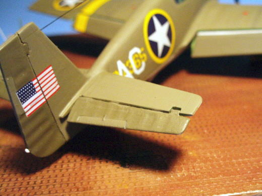
| The elevators after having been
removed, getting a new hinge tab added, and glued back on in an 'at
rest' position. The American flag decal was cut in half to get a more
realistic look where it crosses the rudder hinge point.
|
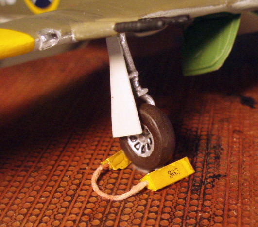
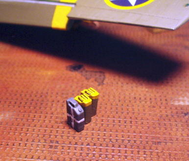
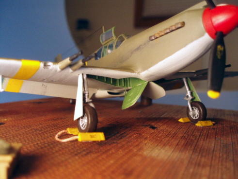
One of those little details - I made wheel chocks out of square plastic stock, joined them with a bit of string tinted brown, and added stenciled-looking decals with the plane's number on them. | |
 |
 |
|
| Another one of those little details, in
this case US-style resin jerry cans with photoetch handles marked as if
they contain oil/lubricant, and a plastic German-style jerry can marked
to signify it contains water (this is North Africa,
remember).
|
A shot underneath to show the wheel
wells, which I detailed with additional plastic strip, and the
retraction rods for the inner gear doors. And those doors are uneven for
a reason. When landing, the inner doors retract flush against the wing.
Being hydraulically operated, though, after sitting on the ground for
awhile they start to droop, and not always at the same rate.
|
|
 |
 |
|
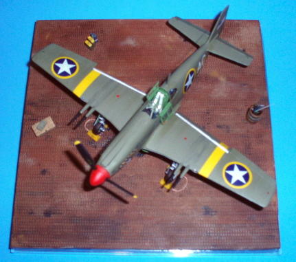
| This overhead view shows the general layout of the finished display. In retrospect, I think I should have angled the PSP on the display base. This looks just a little too squared up for my tastes. | The view I'm sure many Afrika Corps soldiers dreaded - a bright red nose and the business end of four 20-mm cannon, pointed right at them. |
* Maker of Band-Aids, the modeler's best friend!
Addition: This model received a second place trophy in the Propeller Aircraft, 1/72 Scale and Smaller category at the 2008 KVSM contest, in addition to a Best of Show, Propeller Aircraft trophy from one of the sponsors (they really liked the cockpit for some strange reason).
Return to the Modeling Index Page
This page was last updated April 12, 2008.