The K8IQY 2N2-40 meter QRP Transceiver
KC8OANs version
The idea to build this transceiver started with our local radio club secretary Joe, W8DYF passing along some ham radio magazines he had accumulated, including back issues of NORCALs QRPp quarterly. The Winter '98' issue immediately caught my attention with Jim Kortge, K8IQY's 2N2222/40 project with all of its construction details and excellent documentation.
This project was not only a challenge in its construction with the Manhattan style board design, but also an exercise in finding components (followed by some trial and error substitutions such as those required to achieve resonance's within sections of the design). Most parts were in my shop 'somewhere', but some had to be purchased locally, ordered through the mail (toroids especially), and even bummed from Joe and Jack, W8ZRI (thanks guys :-).
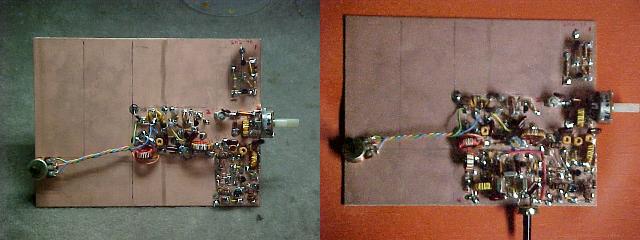
Sensitivity is excellent as evidenced by tuning some weak signals in the lower portion of the 40 meter band on a modern HF rig, and then receiving the same signals on the 2N2-40 with equally good results. Selectivity is also very good, due to the 3 crystal IF filter. Shown below is the outside view of the completed radio.
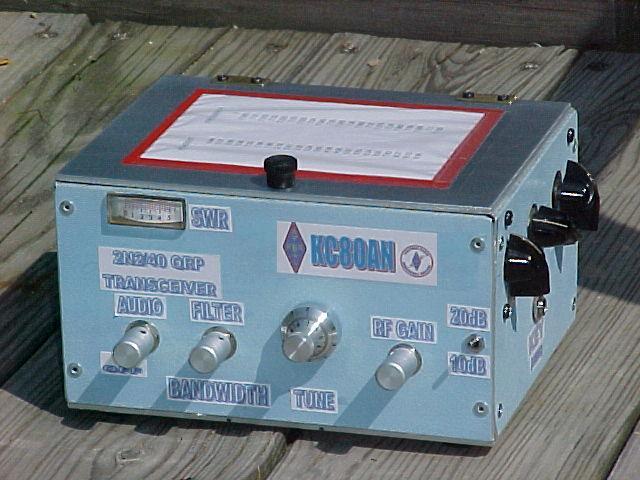
The SWR metering circuit is an addition from Popular Electronics, October of 77 issue. Also on the right side are 3 knobs of a 'T' network transmatch which I threw together to simplify portable operation of the radio. The center knob is a rotary wafer switch which steps through taps of a toroidal inductor (a 1" core, type 6) for a maximum of about 32 microHenries.
The cabinet is made up of pool decking material, with 1/8" aluminum for the top and bottom. The bottom front edge has 2 holes drilled to allow a Bulldog set of paddles mounted on copper clad board, to be solidly held in position by the weight of the radio.
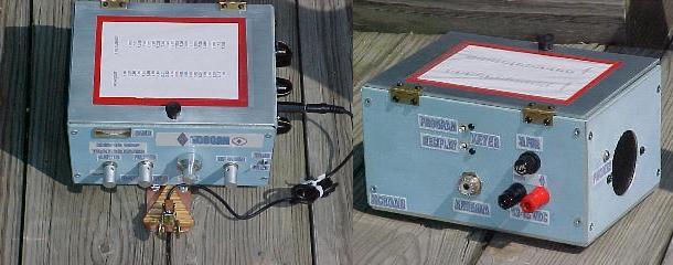
Also included in the circuitry is a keyer built from a kit of WA3ENK's purchased at a nearby hamfest (article was published in June 99 QST, titled 'The QUICK'). Parameters on my unit are via recessed microswitches at the rear. The small board is visible on the inside rear panel.
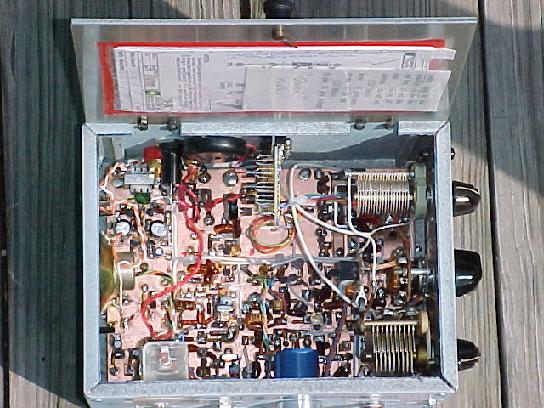
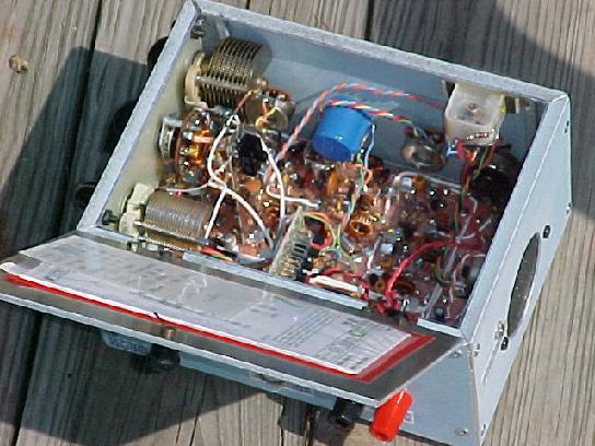
Here is another inside view, but from the front. Schematics are in the pouch under the lid.
Here are a few shots taken, as construction using the
Below is a close-up of the first 4 sections shown above, and the complete board before installation into the cabinet.
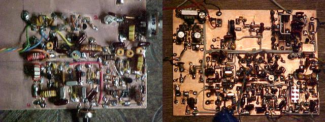
I ended up using a TO-220 case rf power transistor salvaged from an old CB radio, for the final output (in place of the 3 parallel 2n2222's). Also in the lower right area of the overall board is a MiniCircuits SBL-1 mixer (possible use of this unit, in place of the discrete Doubly Balanced Mixer is mentioned in the inset on page 22 of the QRPp article).
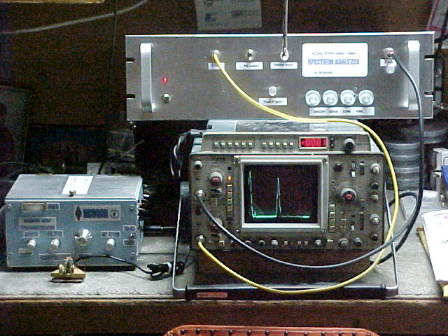
One final picture, the 2N2-40 response shown as picked up through a small antenna, by the W7ZOI / K7TAU spectrum analyzer project shown on this website. Sweep range was set to about 16 MHz, and the screen on the Tektronix 466 scope shows the zero marker on the left, the transmitter output at 7.02 MHz, and virtually nothing at the 2nd harmonic of 14.04 MHz (nice work, Jim & the design crew !).