More on the SPECTRUM ANALYZER
by Mike Whitco, KC8OAN
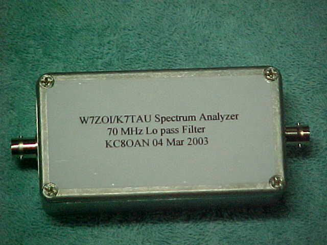
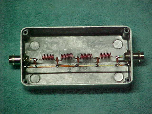
Starting with the first section into which the applied signal enters, we have the 70 MHz low-pass filter (click for outer view).
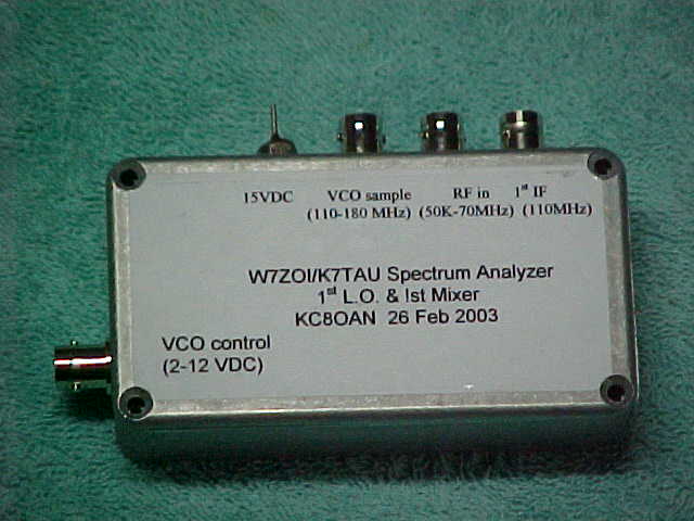
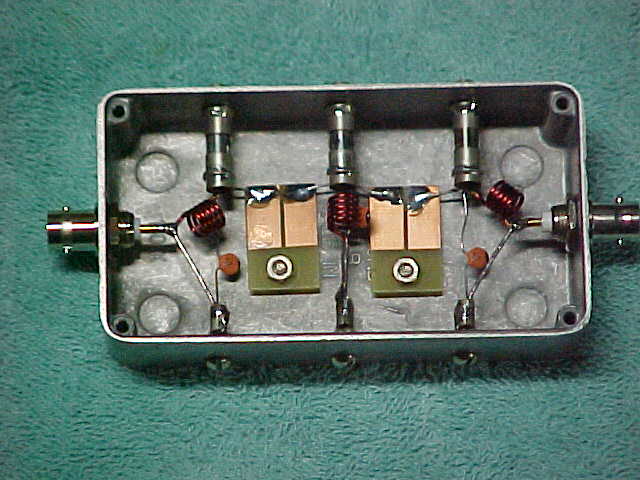
Next in the sequence is the 1st mixer and VCO (click for outer view). It also receives the swept voltage from the Time Base. A bulkhead effect was achieved without the greater space requirement of bulkhead connectors, by creating sheet copper cones soldered around the rear of the BNCs, and to the braid of the teflon coax.

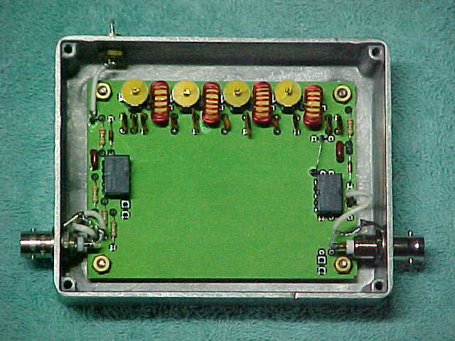
Next is the 110 MHz bandpass filter (click for outer view) shown below.
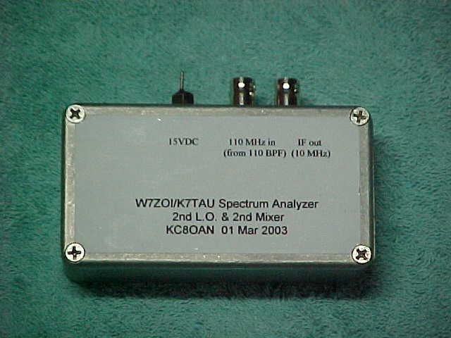
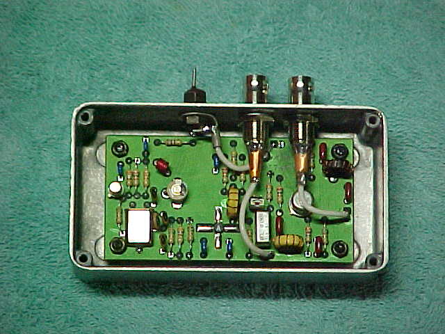
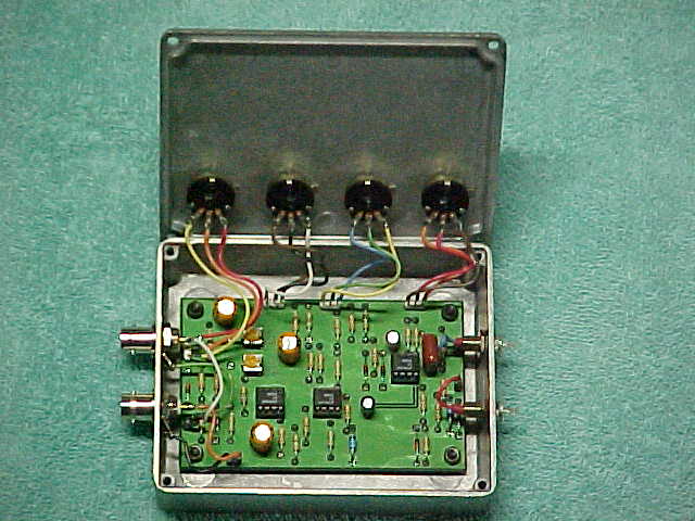
Following the BP filter is the second LO and 2nd mixer (click for outer view). The homebrew BNC bulkheads are much clearer in this photo.
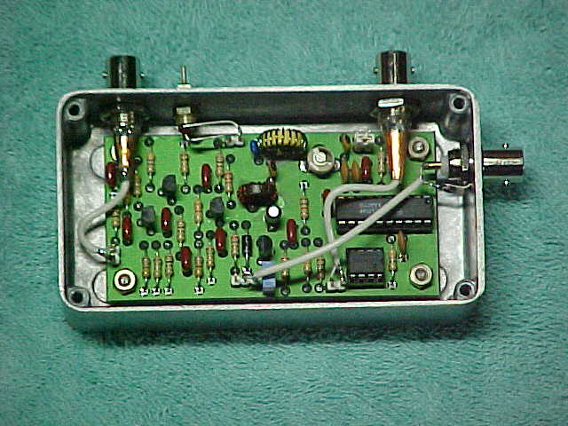
The resolution bandwidth filter (click for outer view) is next, but I am only using the provided 300 KHz filter for now (until I can find a deal on a crystal filter at a hamfest...hi).
The IF and Log Amplifier stage (click for outer view) is shown below (no bulkhead was used for the front panel mounted IF gain pot connector).
And finally, the Time Base (click for outer view) shown below. I added a 20k pot (on the front panel) at the X output to the scope, to allow for adjustment to fit the width of the scope screen.
All sections are mounted in the overall chassis with brass screws through their bottom edges.