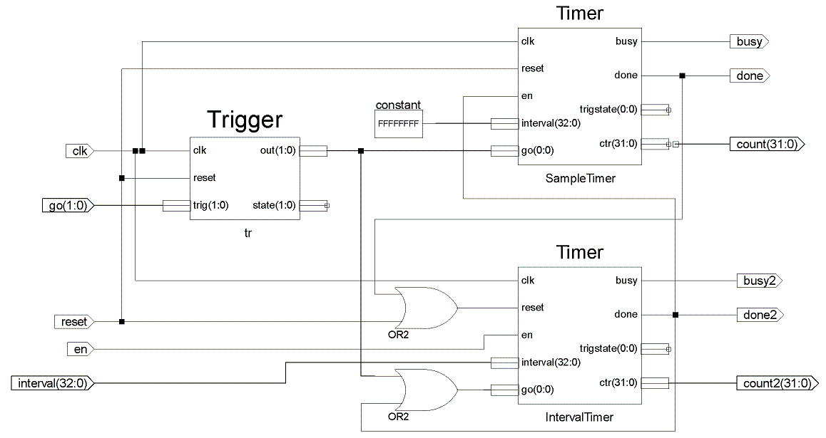
Delivers a defined number pulses at programmable intervals. The number of pulses is fixed at build time, while the interval between pulses can be changed on the fly. The internal interval counters, and busy and done signals are available. A multi-level trigger may be input (Trigger.v).
Ports | Parameters | Notes | Example | Timing diagram
| clk | input | The clock input. |
| reset | input | Reset input, which restores the idle state to both the timer itself, and its trigger logic (Trigger.v). |
| en | input | Enable; the timer's state is frozen when not asserted. |
| interval | input | The interval between pulses. |
| gonow | output | The output of the trigger module that signals the actual start of counting. |
| busy | output | Timer is running; not asserted while awaiting triggers. |
| count | output | The pulse timer, which counts to terminal_count. |
| done | output | Done; asserted when the interval is counted. |
| busy2 | output | The state of the interval timer. |
| count2 | output | The internal counter of the interval timer, which counts to interval before restarting. |
| done2 | output | A pulse indicates the terminal count of the interval timer, whose output port is count2. These pulses are counted by the pulse counter, whose output port is count. |
| width1 | 11 | The bit width of the internal pulse counter whose output port is count. |
| width2 | 16 | The bit width of the internal interval counter; it must be large enough to hold interval-1; the width of interval is one greater so that it can hold 2width2. The counter's output port is count2. |
| gobits | 1 | The number of triggers; see Trigger.v. |
wire			clk, reset, en,
wire			go1, go2, go3;
wire	[17-1:0]	interval = 48932;	// one wider than width2
wire	[10-1:0]	address;
wire			DoSomethingPeriodically;
DoubleTimer
    #(.terminal_count(1024), .width1(10), .width2(16), .gobits(3))
    cntr_addra (
        .clk(clk),	.reset(reset),	.en(en),
        .interval(interval),
        .go({go1, go2, go3}),
        .count(address),
        .busy(busy),
        .done(done),
        .done2(DoSomethingPeriodically)
    );
The diagram below shows the design of the module. The timing diagram shows a testbench simulation of two instantiations, one with constant interval of five, and the second with a variable interval. The testbench is in the Testbenches directory of the repository.

