This module limits the magnitude of an I/Q data channel while preserving its phase. It takes as input a signed I, Q, -I, -Q sequence signal and outputs a signal whose magnitude is at most a given value (specified at compile time) while preserving its phase. It uses a serial Cordic rotator, so there is lag of about 1/3 μs.
Ports | Parameters | Notes | Example | Plots
| clk | input | The clock input. |
| reset | input | The reset input. |
| en | input | The enable input. |
| go | input | Initiates operation of the limiter. The limiter retriggers itself after it is started. |
| quad | input | Two-bit quadrant counter. |
| in | input | The input data stream. Its width is given by the width parameter. |
| out | output | The output data stream. Its width is given by the width parameter. |
| busy | output | Indicates that a rotation is in progress. |
| done | output | |
| active | output | Indicates that the limiter is actively limiting the output. |
| diag1 | output | A floating diagnostic output. |
| diag2 | output | A floating diagnostic output. |
| width | 16 | Bit width (default 16) of the data input and output. |
| steps | 11 | The number of clock cycles through which the Cordic rotation runs. It must be -1 modulo 4 at this point (7, 11, 15, ...), but it need not be greater than the number of data bits. |
| mag | 11319 | The magnitude at which the I/Q data are limited. It must be in the range of the data. |
| msbs | 4 | Because the Cordic converter becomes unstable for small input signal intensities, it is disabled when the input intensity is below a threshold given by 2-msbs smaller than full scale. |
localparam w = 16;
wire			[w-1:0]	in, out;
Limiter
    #(.width(w), .mag(10720), .steps(w-5), .msbs(4))
    lim1 (
        .clk(clk),
        .reset(reset),		.en(1'b1),
        .go(startpulse),	.quad(quad),
        .in(in),		.out(out),
        .busy(busy),		.done(done)
    );
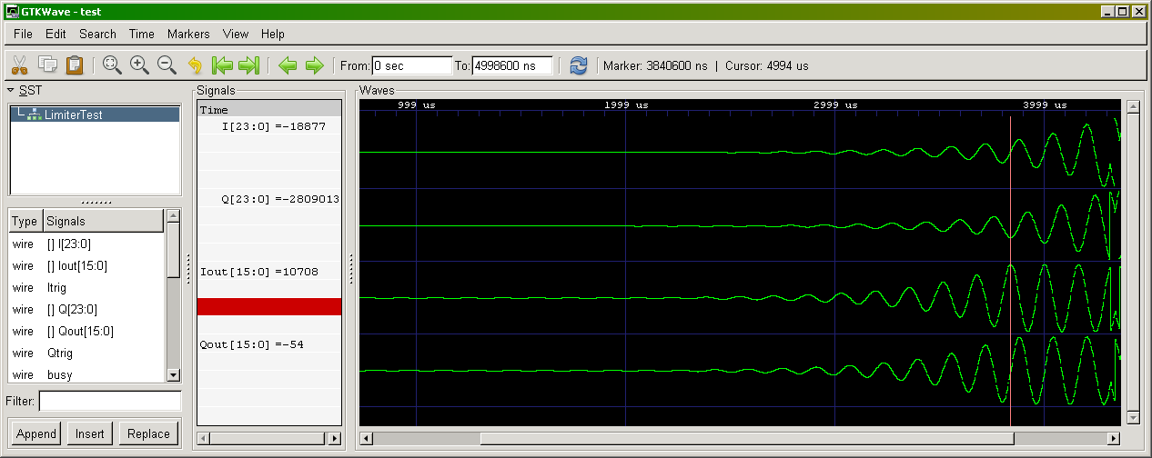
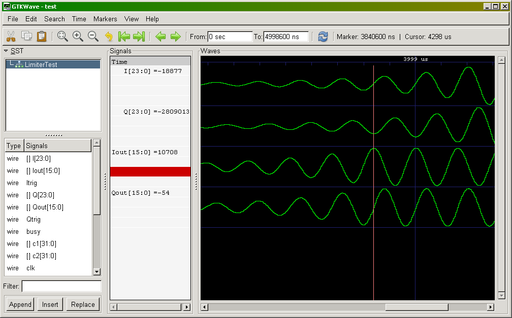
Plots of simulations.

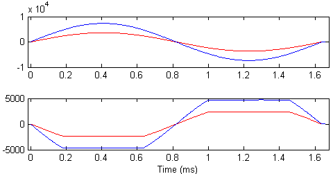
I/Q plots of limiter input and output run on the controller board. There is sinusoidal modulation applied.