This module adds the phase of a reference signal to a setpoint signal. The reference signal is averaged over many samples prior to the operation. When the reference accumulation is done, the Cordic rotation is initiated.
Data outputs are initially all zero. The go input initiates an accumulation cycle, after which the a Cordic rotation is initiated. Cordic rotations are subsequently automatically retriggered, unless the Testbench symbol is defined by a Verilog directive.
Ports | Parameters | Notes | Example
| clk | input | The clock input. |
| reset | input | Reset input, which clears the accumulator and resets the module's state to the idle state. |
| quad | input | A two-bit quadrant fiducial. |
| go | input | Initiates an accumulation cycle. It may be a multi-bit vector whose width is the gb parameter. |
| in | input | The data input (setpoint) port of w1 bits width. The phase of the reference input is added to this signal. |
| inMag | output | The magnitude of the in input scaled by 1/0.607253. It has the same bit width as in. |
| ref | input | The reference input whose phase is added to the in input. |
| refavg | output | The reference input averaged output by the internal accumulator. Its width is the same as the in input. |
| Iout | output | The in-phase (I) output. |
| Qout | output | The quadra-phase (Q) output. |
| IoutN | output | The twos-complement negative of the in-phase (I) output, synchronous with Iout. |
| QoutN | output | The twos-complement negative of the quadra-phase (Q) output, synchronous with Qout. |
| out | output | The I/Q output with the ++--... modulation for fs/4 upconversion. |
| busy | output | This output indicates that a Cordic cycle is in progress. |
| done | output | A pulse that indicates that a Cordic cycle has completed and data are valid. |
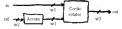
The figure below illustrates the usage of the bit-width parameters.
| w1 | 16 | The bit width of the in input port. |
| w2 | 16 | The bit width of the ref input port. |
| w3 | 16 | The bit width of the five output-data ports. |
| ofl | 10 | The number of accumulator overflow bits. The number of accumulation clocks is tied to this parameter: cycles = 2ofl. |
| apb | 5 | The number of accumulator precision bits. These bits on the lsb end of the accumulator participate in the addition of samples, but are discarded at the end of the cycle. This is done to preserve precision of the output. |
| gb | 1 | The number of bits in the go vector, which may be a multi-level trigger. |
| direction | 1'b1 | Whether the module adds the reference phase (1'b1) or subtracts (1'b0) to the set point. |
localparam		wid = 16;
wire		[wid-1:0]	Iout, Qout, out;
wire				g, busy, done;
ReferenceProc
    #(.w1(wid), .w2(wid), .w3(wid), .ofl(8), .apb(4))
    rpinstance (
        .clk(clk),		.reset(reset),
        .go(g),			.quad(quad),
        .in(data),		.ref(d1),
        .Iout(Iout),		.Qout(Qout),		.out(out),
        .busy(busy),		.done(done)
    );