Current Carrying Capacity

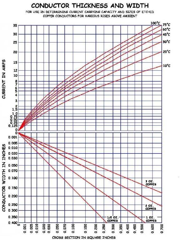
This chart and the graph below it display
the current carrying capacity of copper clad circuit boards as originally
specified by MIL-STD-275, which has now been replaced by IPC-D275.
|
Copper thickness |
½
oz. = 0.0007 in. |
1
oz. = 0.0014 in. |
2
oz. = 0.0028 in. |
||||||
|
Temperature rise above ambient |
10° C |
20° C |
30° C |
10° C |
20° C |
30° C |
10° C |
20° C |
30° C |
|
|
|||||||||
|
Conductor width in inches |
Maximum
current carrying capacity measured in Amps
|
||||||||
|
0.010 |
0.5 |
0.6 |
0.7 |
1.0 |
1.2 |
1.5 |
1.4 |
1.6 |
2.2 |
|
0.015 |
0.7 |
0.8 |
1.0 |
1.2 |
1.3 |
1.6 |
1.6 |
2.4 |
3.0 |
|
0.020 |
0.7 |
1.0 |
1.2 |
1.3 |
1.7 |
2.4 |
2.1 |
3.0 |
3.6 |
|
0.025 |
0.9 |
1.2 |
1.5 |
1.7 |
2.2 |
2.8 |
2.5 |
3.3 |
4.0 |
|
0.030 |
1.1 |
1.4 |
1.7 |
1.9 |
2.5 |
3.2 |
3.0 |
4.0 |
5.0 |
|
0.050 |
1.5 |
2.0 |
2.6 |
2.6 |
3.6 |
4.4 |
4.0 |
6.0 |
7.3 |
|
0.075 |
2.0 |
2.8 |
3.5 |
3.5 |
4.5 |
6.0 |
5.7 |
7.8 |
10.0 |
|
0.100 |
2.6 |
3.5 |
4.3 |
4.2 |
6.0 |
7.5 |
6.9 |
9.9 |
12.5 |
|
0.200 |
4.2 |
6.0 |
7.5 |
7.0 |
10.0 |
13.0 |
11.5 |
11.0 |
20.5 |
|
0.250 |
5.0 |
7.2 |
9.0 |
8.3 |
12.3 |
15.0 |
12.3 |
20.0 |
24.5 |
|
|