Brad's Z-activities Site - The Central End Module - Design and Construction
Updated: March 17, 2007
Jump to latest updates
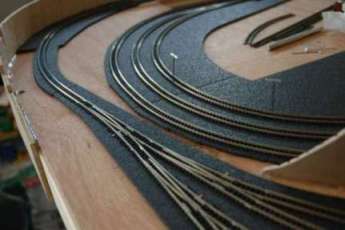
This, my second major module development, introduces a freight and service yard on one side and a passenger station setting on the other. This project began in July 2006 and reached an initial operational state in time for the February 2007 WGH on Tour Show in Portland, OR.
Layout Design (July 2006) - Grid represents 4" squares (image quality reduced) -- black tracks represent the through mainlines.
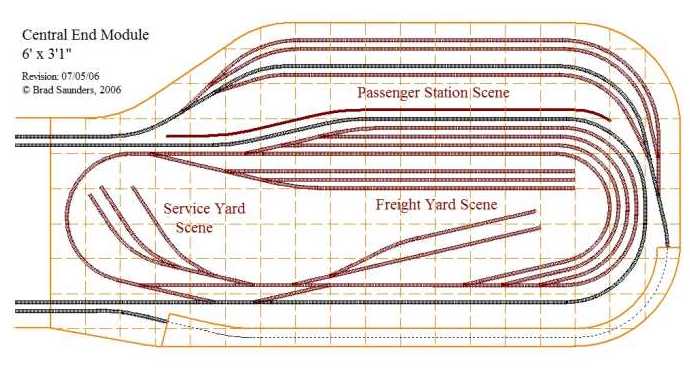 I chose to design this as an end module for a couple of reasons. First, I could easily use a new end module for my home modular layout to replace one of the utility end modules that I've been using to date. Secondly, I found that the looping of the freight yard area needed some additional depth that was more readily accomplished in a bulging end rather than making an unusually thick straight module. It also allowed me to gain some added length in the passenger sidings.
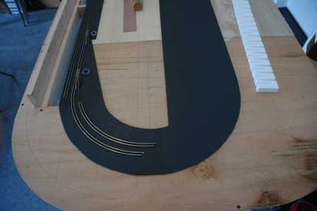
Something that you'll likely notice right off is the mainline at the bottom dissappearing under something that appears to be a lid or cover ... this is actually a key feature of the design in that it is intended to protect the outer "passenger" mainline from the giant operator working the freight yard which is situated off of the inner mainline. I'm planning to expose the hidden mainline via a viewing window on the side of the module.
The thick line separating the Passenger Scene from the Freight Yard Scene is a visual block ... this feature will be built as a two-sided backdrop, presenting the appropriate scene when viewed from each side of the module. I plan to build a passenger station structure extending out from the backdrop on the one side and the other side will show an extention of the yard scene. The freight yard is designed so that it can be operated separately from the mainline ... the intention being that an operator can be setting up consists for routing out to the mainline and subsequently receive consists from the mainline for sorting and re-routing.
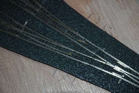
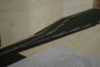
There are 24 turnouts in this design. Due to the need for highly reliable performance in a show environment, I've chosen to go with Wright Turnouts which I'll set up to be operated via remote manual throws. Being a substantial number of turnouts, the first thing I did before even starting construction was to place my order with Peter. I ordered the Marklin-compatible turnouts as I intend on using Marklin flex for most of the trackage, this will be consistent with the Canyon Module trackage. The hot frogs of these turnouts are usable without special consideration although better power delivery to the frogs is assured if simple power routing is incorporated into the setup via the extra power tab that is provided ... more on this later when we get to turnout installation.
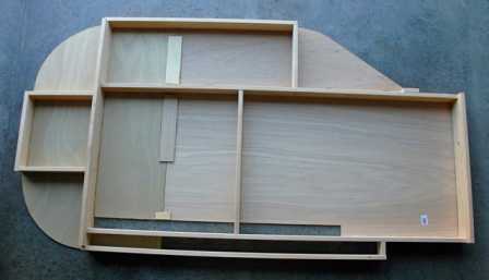 Couldn't wait to start framing up the module ... this photo showing the underside structure. The framing is a bit light at the moment and I'll hold off adding any more structure until a bit later after determining where the weaker points are after adding the side paneling.
Once again, I'm using hemlock for the framing and I've taken special care to select each piece by lightest weight as I found that there was quite a difference between the boards in stock at my local lumber yard.
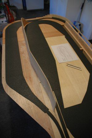
Its not easy to get the scale of size from this photo ... referring back to the plan above, you will note that the module is 6 feet long and it required cutting up three 2' x 4' panels of 1/4" thick material to make the surface, the better side of those panels exposed to the underside since this will be exposed when the module is complete.
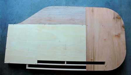 This view from the top ... you'll probably note a couple of uncovered sections (those narrow areas near at the bottom edge of this view. One of these will be filled shortly to provide the path for the outer mainline, the other is actually where the yard power and turnout controls will be framed in as part of a control panel.
You'll note that there is no pink foam. This particular module is essentially flat so I felt no need to add the thickness of foam into the design. I'm not absolutely sure that I won't want to have a feature or two get below the module surface and if so, I'll simply cut that section out and add appropriate sub-structure to make it work ... for the moment, I don't think that I'll have anything like that to do.
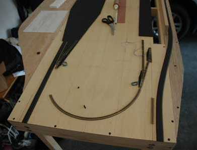
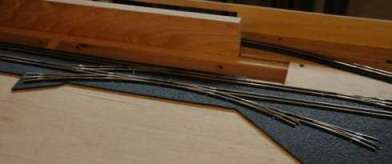
 So, I'm cheating here a bit by using some Marklin turnouts (as temporary stand-ins for the Wright turnouts being constructed for this module) and other track segments to do some planning as I transferred some of the tracklines to the module surface. This photo is in the area of the first turnout along the inside mainline in the lower left portion of the plan. What I was trying to visualize is what was going to be the final spacing between the mainline and the baseline track of the yard inside of it. The plan started with the center line spacing at 2" and after this experimentation, I've decided to reduce that to roughly 1.4". Actually, I'm going to use two Marklin 25mm long track sections between the turnouts to establish the spacing ... this will also make it easy for me to simply insert insulated rail joiners to create the needed block gap.
 As with the Canyon Module, I'm using Woodland Scenics N-scale foam roadbed. Here you can see some fairly large pieces of that material installed, these areas being where a large section of yard sidings are planned. Although I did some visualizing with sectional track seen here, the final track installed will be flex and specifically placed to maximize the curve radii.
The 2' piece of foam riser seen in the photo is not really going to be used on the layout but I did use it for identifying some of the track lines. You can see a faint curved line drawn on the lower left side of this view, this line is for the outer mainline on the lower right portion of the layout plan. I often use the foam risers as a flexible sighting tool, in this case I pinned it down along the straight edge (at the left) entering the curve and similarly pinning it down at the opposite end coming out of the curve, adjusting the placement of the material at this end as needed to get a smooth curve naturally resulting from the springy characteristic of these risers.
 The other end of the module is seen here. The roadbed at the right is the outside mainline transitioning out into the covered portion of the track plan. The "S" curve of this line was established using my springy riser technique, the result being a very gentle set of curves with some easements separated by roughly 6" of straight between them.
One of the reasons I was playing with the track spacing (between the inner mainline and the yard baseline track) was to establish as large a radius for the loop-back curve in the yard. The position of the turnout at the entry to that curve being moved slightly right added an estimated 1/2" to the radius such that it ended up roughly equal to the standard sectional 195mm radius.
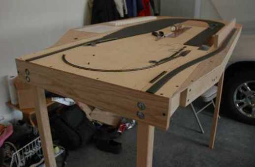 This view provides a bit more perspective on the developing module. You can see the legs attached on this end with recessed bolts (so that this module will attach properly to the next module). The legs are a bit unstable as they are seen here, I'll be adding some cross-bases a bit later on to correct for this and added stability will come with the module attached to the rest of the layout.
No side panels installed yet but I expect to add these relatively soon. This is because the side panel on the right side of the module makes up a critical part of the structure which will hide the outer mainline as it runs around the outside of the service and freight yards. The board seen rising up from the module surface is the back wall of the hidden section and provides much of the strength that will be needed for the "armrest" for the yardmasters as they work setting up the freight consists.
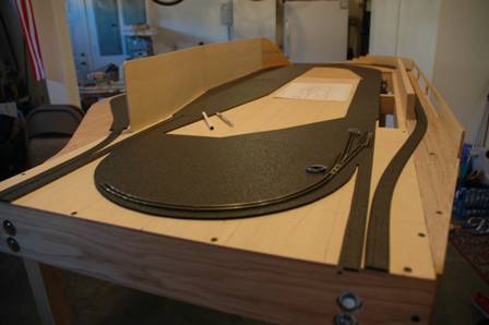
 August 2006 - Here we are a couple of weekends later and most of the roadbed surfaces are now in place. Additionally, I've completed the basic construction of the backdrop divider that separates the passenger station scene from the freight yard scene.
To the left you can see an earlier step where I used the flexible foam riser to help sight the mainline transition into the passenger section of the module. I aligned the edge of the foam with the straight entry to the module and pinned it in place. Then I flexed and pinned the foam along the straight path of the first turnout, adjusting its position to get a curve along the general path that I had planned. Finally, I gently lift and wiggle the foam in the middle to allow it to adjust to its natural resting position followed by sketching in the line along the foam edge. The result is a transition curve with some gentle easement entry/exit transitions near the straight portions. Its effect really quite subtle given the scale but upon close inspection it seems to accomplish the easements without having to draw them out on the surface using the line and radius offset approach.
To the right is an overall view of the module. Here you can readily see how the divider will provide visual separation between the two main scenes. The divider is only 6" tall (110 scale feet:o) but given that the base level of the layout is 50" above the floor, this relatively low divider is still reasonably effective when viewing the module. On the passenger side you can certainly rise up on your toes to see the yard on the other side (or if you are very tall, you'll certainly see portions of the yard) but hopefully the observer will not focus on that. From the freight yard side you can't readily see the passenger side at all given the divider is set way back in the module (from that side). BTW, the divider is made from the same surface material as was used for the module and the module sides, that being 3/16" luaun panels. To get the bends in the panel material, for the divider as well as for the module sides, I make a series of shallow cuts in the panel on the surface side which is to the inside of bend. This makes it easy to flex through the curve although it obviously doesn't leave a smooth surface where the cuts are. For the module side panels, these cuts are covered up to that they aren't seen anyway, for the divider, I'll simply fill the cuts to smooth out the surface before painting or covering it to create the backdrop scene.
 The roadbed is generally complete with the exception of a pair of sidings in the middle that I've not got final placement on. If it seems like there is more roadbed than what you would expect, let me first point out that I can cut out any excess after laying the track in place as it cuts and peels off the wood base quite easily. I secured the roadbed with craft tacky glue. That said, I do however plan to keep the roadbed as a solid surface throughout most of the siding areas as usually in such areas the ballasting is much lighter and distributed evenly unlike the elevated profile of the mainlines. On the passenger station side, I actually have to add the usual platforms and I'm expecting to simply install them over the roadbed between the tracks although I will likely cut out some portions (and even through the module surface) to model the passenger underpass tunnels for getting to each of the lines from the station.
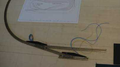
At this stage I'm anxiously waiting the delivery of my first set of turnouts from Peter (they've been shipped, yeah!) so that I can proceed toward laying some of the track. Meanwhile, I've still got some prep work to do regarding the control panel which will fill the gap visible in this photo just to the right of the inside mainline.
 Well, the Wright turnouts are here and they look just great! Its been a few weeks since my last posting and the second set of turnouts are here as well so all 24 turnouts in the module design are accounted for.
This view of the layout shows the first three turnouts installed for entry into the passenger station scene. Along three of the branches are the initial pieces of flex, each of which is 26 inches in length. The turnouts are held in place using a thin layer of tacky glue so they will remain easy to lift up if ever needed to be repaired or replaced (certainly hope not:o) while the flex track is being held down using CA applied between the ties every so often as needed to maintain the desired track line. Even using CA, I suspect that the track can be lifted without too much effort given the foam roadbed and the fact that I didn't get too carried away with applying the adhesive.
 Another view, this time with all of the passenger station lines layed and three turnouts at the far end installed as well.
I adjusted the spacing between the track lines a bit from the layout plan, moving the parallel track lines a bit closer together than the typical 1" default spacing in order to be a bit more realistic. I also adjusted the platform gap between the two pairs of tracks to approximately 25 scale feet. Between these two changes, I was able to make a bit more space between the tracks and the divider backdrop to provide more modeling space for the passenger station.
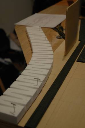
Eventually there will be three passenger platforms (one down the outside track, one down the middle and one on the station building side) connected by pedestrian underpasses so that passengers aren't crossing the tracks. Each platform will have the usual gathering spaces with seating and portions covered.
As seen in this view, the third track from the left is optimized as the through mainline with all of the turnouts in this particular line set for the straight path.
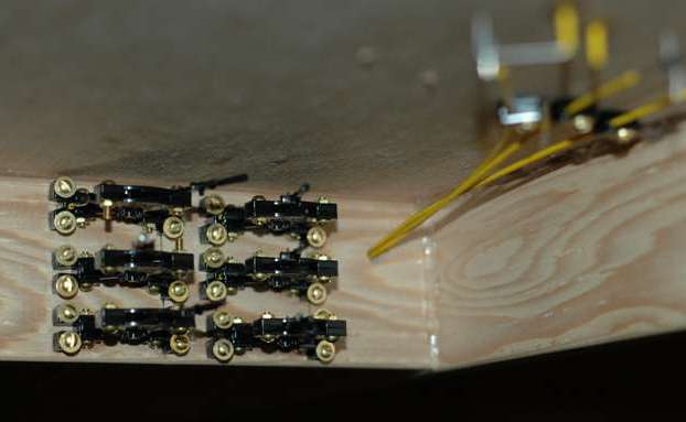 Turnout controls for the passenger side of the module will be hidden under the layout although in easy reach of the operator. The turnout controls use Hump Yard Purveyance mechanical track turnout levers (http://www.humpyard.com/), six of which are needed for the passenger side of the module. I've set up the levers so that without actually having to look under the module to see them, an operator will be able to readily determine what position all six of the turnouts are in based on the order of the level and which way it is set (to match the position of the points).
These controls are sold as HO and N-scale controls but I could see no reason that I couldn't adapt them to Z-scale as well. As I've found out, they are certainly adaptable but it does take a bit of care to adjust for the smaller range of motion required for Z-scale points.
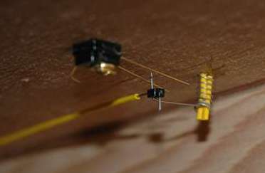
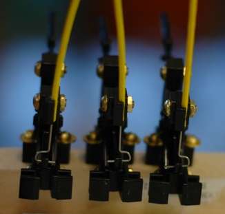
 Here is the underside of the first turnout control setup. You can see the cable coming in from the lower left and linking in with a wire arranged as a bellcrank lever going up to the turnout points above. This wire is quite stiff and takes a bit of effort to bend into the shapes that I needed but of course its that stiffness that is needed for the push-pull-twist action to work effectively.
Also in view is the electrical power routing arrangement which is based on the movement of the bellcrank wire between two contacts, all of which still need to have the power wires soldered to them to select the power for the hot turnout frog. This power connection is redundant to the power which actually passes from the main rails into the frog via the points contact. More on the power routing later.
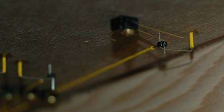
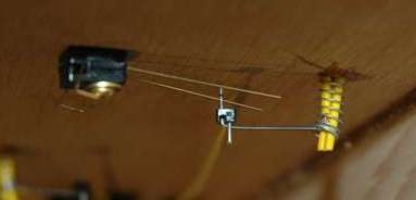
 From this topside view, you can get a better idea of what I mean by a bellcrank control. The wire feeds vertically up through a piece of teflon sleeving and then is bent over to hook down through the control loop that is directly connected to the points of the turnout. The range of motion, side to side, of this control point is slightly more than a 1/16 of an inch.
The key to getting this to work is getting the ratio of the horizontal length of the wire on top (from the control point back to the vertical shaft) to the horizontal length of the wire below the layout to the linkage point with the control cable set such that the control lever range of motion (slightly more than 1/2 of an inch) is in proper proportion with points range and yet retain some tension in the wire to keep the points in proper contact. A bit of experimentation prior helped me work this out before commiting the setup to the actual module installations although I've already found out my ability to get it right each and every time is in doubt so I'm prepared to carefully cut out failed attempts to start anew. Each lever kit came with plenty of sleeved wire so I'm not too concerned with running out.
 September 2006 - The primary reason for this update is to talk about the turnout control design improvements that I've made.
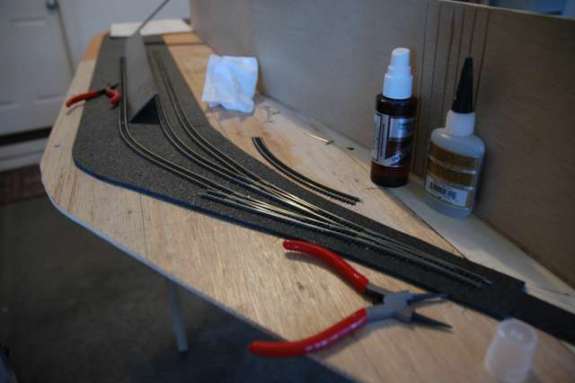
But before that, here are a couple of pics showing some of the progress made on track layout and turnout installations. All 24 turnouts are now in place ... the photo to the left is of the set of turnouts that branch out to the back of the yard.
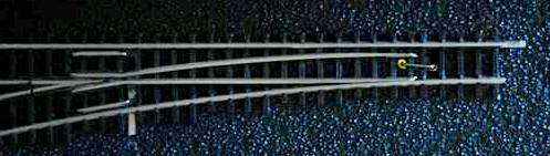 Here is a straight down view of the installed turnout ... the yellow teflon sleeve is visible with the control wire coming up through it. The wire bends at 90 degrees toward the right and then bends down 90 degrees again through the control loop on the Wright turnout. The top of the teflon sleeve is actually sitting down flush with the top of the roadbed and I believe that I can generally disguise it with ballast in a later step.
 A couple of views from underneigh the turnout ... here is where the key improvement has been made.
It turns out that the bellcrank wire tends to ride up in the teflon sleeve and the wire above the turnout will rise up a bit with continued usage. The improvement is to add a spring to the underside that applies downward pressure to keep the wire from rising above. The new spring is positioned over the sleeve as it extends below the layout ... I've had to add some addition pieces of sleeve material to extend below the bend in the wire such that it "locks" in the spring from trying to follow around the bend in the wire. All of the teflon sleeves are held in place with CA glue, taking care not to get any down near where the wire comes out.
 With the mechanical aspects of the linkage now in place, turnout operation appears to be smooth and reliable. I'm glad that I've chosen a bellcrank arrangement for the control as this approach reduces the chance of pushing the points upward. Slow operational movement of the points is easily accomplished simply by moving the cable control lever slowly.
The electrical contact setup visible in these photos is not complete with wiring ... soldering comes later in the process.
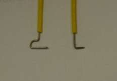 Another modification that I've implemented with the Hump Yard Purveyance controls is shown here. One thing I didn't like with the first few levers that I installed was how the wire seemed to bind or get laterally stressed as I moved the lever in the direction where the wire is pushed furthest into the teflon sleeve. To relieve this stress on all of the remaining levers that I'm installing, I've modified the shape of the wire where it is attached to the lever ... in these images you can see the hook shape that I now use (as opposed to the simple 90 degree bend shown in the lever instructions). These hooks now allow me to position the wire on the lever such that the wire moves smoothly in the sleeve. Before, the wire was pushing the lever sideways and making it harder to change the position of the control.
Now I am working on installing all of the remaining turnout controls. Once I have that completed, I'll have one more thing to share about installing them as I've got two instances in the layout where a single lever will be controlling two separate turnouts at the same time.
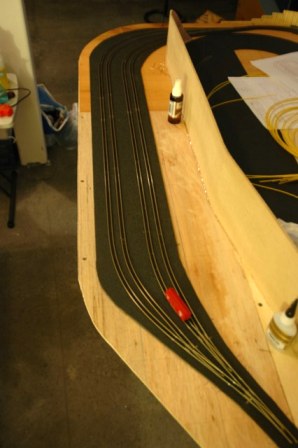
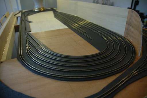 All of the main track lines are now installed. There remains some stubs to install but for now I'm holding off on those until after I figure out what structures and details around those stubs are to be located before finalizing the track positions.
Getting all of these yard tracks in place was a bit tedious and I had to take care as to maintain the smooth curves as I systematically worked through each line starting with the outer most track and working my way toward the inner most track. These tracks are held in place using CA glue added under the ties about every 3 inches or so, allowing each glued portion to set before working around the curve toward eventually hooking up with the straight sections in the back of the yard. I used a spacer (my old Micro Trains rerailer did the trick:o) to maintain the desired separation between the track lines.
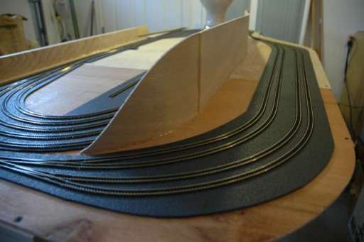
Those yard siding stubs on the right have yet to be extended to their final length. I'll extend them once I finalize how I'm going to end them with regard to the end-of-line bumpers.
 Another view of the completed track installation is shown on the right. The passenger station section is to the right of the backdrop divider and what can be seen of the freight yard is to the left.
Finally, below is a view of the section of the yard where I've yet to install the stubs.
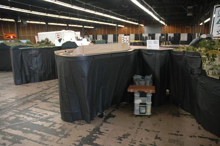 March 2007 Update: Seen here is a view of a portion of the CZM modular layout at the WGH on Tour Show held recently in Portland. The Central End module is at its first show while the more experienced Canyon Module (seen to the right) is once again called into service. At this point, we are still using plastic table cloths for skirting - since the show, I've acquired fabric which I'll use to make permanent skirting in time for the next show (LOTS National Convention Train Show in July).
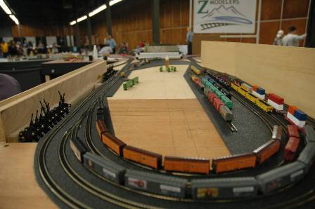 Although not fully wired, the freight yard still served a useful purpose as a staging area. Using a five-finger technique, assembled consists could be brought around to the mainline (which was fully functional) and hooked up to an engine for running over the 5+ mile run we had setup on the inside loop.
At this point, all of the turnout controls are in place and functional. I've found that each turnout control required some attention to tuning them for proper operation to make sure that the points align flush to the appropriate rail when the control lever is in its final position. These controls have been a bit of challenge to get right but they sure look good and lots of show visitors were quite interested in seeing them in operation.
© 2007 Brad Saunders