Much of the P&W-RR structure is being built on a foam base and with foam incline grades. All of the products use in this particular layout come from Woodland Scenics which are readily available at local hobby supply stores. During the course of building up the layout, I'll use this section of the site to share my experience with the use of foam and hopefully some interesting tips and techniques.

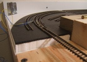 In these pictures you can see the yard shelf with a layer of 1/2" foam topped by sheets of N-scale foam roadbed. I've chosen to attempt to use the N-scale foam roadbed instead of Z-scale cork roadbed ... primarily because it is much less expensive and easier to use. In the yard area, using sheet material makes a lot of sense versus laying individual tracks of roadbed material. Actually, a good portion of the sheets shown here will be cut away as I finalize the tracks and add some beveling cuts where needed to improve the look that will appear with the addition of the ballast.
One thought that you may have is that the N-scale material is too thick and wide to be used as Z-scale roadbed ... fair enough, I initially thought that too. After thinking further I realized that I could easily cut beveled edges where I needed them widthwise and that the height disparity can be easily accounted for by not running the plaster cloth (to be added later) under the roadbed but rather up to the side of the roadbed (and taking up the height difference). Hopefully what I plan to do will be more obvious later when I get to adding the ground surface (and not a disaster in the making!:-)
 In this photo you can see that I've extended the 1/2" sheet foam for the initial portion of the main part of the layout where the track remains level. Following that there is the first section of foam incline material which introduces the initial 1% grade transition. This first incline section was made by stacking (and gluing) a portion of 2% incline on top (and in reverse) of a 3% incline piece to effectively get a 1% grade. Care had to be taken to make sure that the mating edge to the level foam started at 1/2" in height and I only glued the mating vertical edges (between the level sheet and incline riser) together at this time to allow for the riser on the right to be flexed in the direction I need later when following the track route.
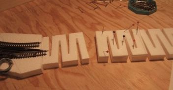 Here the next section of the incline can be seen as it is being built-up. Only the first 3 inches of the incline has been prepared (seen pinned down while the glue sets) by stacking a 2% incline section on top of 1/2" level riser. The remaining portion of the 1/2" riser will have some 3% material stacked on it to ultimately reach my next grade transition planned for 21 inches from the initial start of the 1% grade (and running total elevation of 0.56", or about 10.25 scale feet).
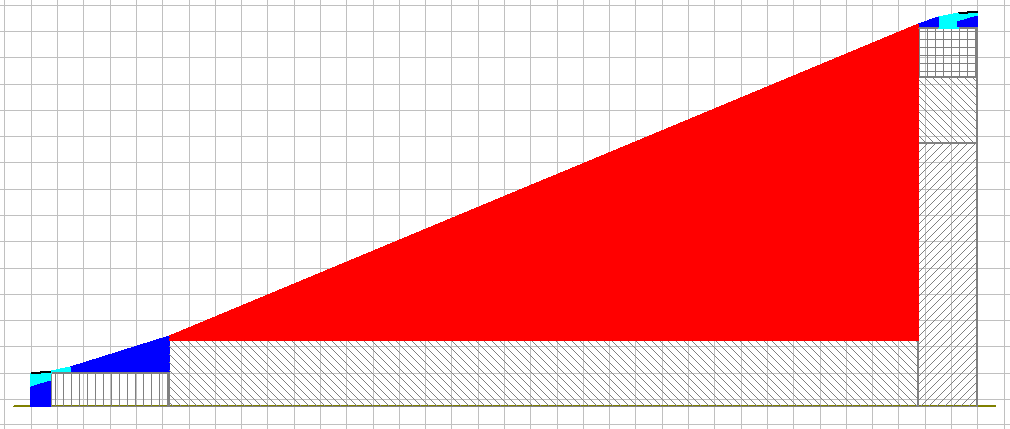
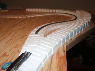 As work continues you can see the Northside grade building up. As I did this section I discovered that creating a graceful route was easier to accomplish by using the foam riser's natural tendency to average out bends. Even better, I found that if I glued together a couple of the 24" sections that it was easier to work out the complete run. At key target points on the layout (for example closest points to the edge or positions of switches), I would temporarily pin down the foam and let the rest of the foam find its natural position based on the flex characteristics of the foam (note the zig-zag pattern in the foam as this tends to make it act like a spring). The more you stress the foam to make a tighter curve, the more circular the shape that forms, the less stress the straighter it gets and transitions between the two tend to form graduated spirals. This latter effect helps to establish reasonable easements into and out of curved sections of track.
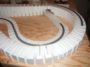 Continuing further, you can see that the lower industry track has finally crossed under the rising Northside grade. Based on the layout plan, this industry track will disappear behind the industry structure only to reappear from behind the matched industry on the Southside of the layout. The rather crude foam cutout under the Northside grade will be modified as needed to allow for clear passage of the trains that will take this industry route as part of an loads out/empties in operational scenario. All of this will be covered over by the mountain onto which the Northside grade ascends.
BTW, the foam is being attached to the board using a hot glue that is a low enough temperature as to not damage the foam. I'm using the Woodland Scenics product for this but a number of other glue guns and sticks will also do the trick. Some of the higher sections in this picture are not glued down just yet and pins are used to hold them temporarily in place. I won't glue on the section above the industry route until after the lower track is fully installed.
As the work continues, more examples of the use of foam will be shown along with tips and techniques that I pick up along the way.
| Return to Start |
|