The layout design very closely follows the design that John Armstrong wrote about in an article1 he did about what might be possible using Z-Scale modeling. I believe that this article was originally written prior to 1990, going back to when the Micro Trains product line was still sold under the Kadee brand. The design is based on a fold-up concept whereby the majority of the layout is stored upright above a connecting shelf in order that its out of the way when not in use - a great space saving idea. In the drawing shown below, the shelf is to the right and the large blocks shown represent an elevated hinge system for allowing the layout to fold-up without concern for interference at the mating surfaces.
Areas where I significantly differed from John's published design include the approach to the yard section (shown on the shelf to the right) and the grading. I chose to reduce the number of tracks which would cross the hinge gap from 6 down to 4; with this change came a restructuring of the yard with the incorporation of additional switches at both ends of the shelf in order to get ready access to the third main line going through the yard.
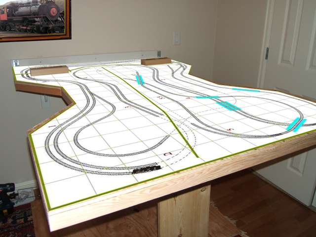
Regarding grades, John's design assumes two basic grades : 3.6% on the steep side (shown above the middle scenery backdrop) and 2.1% on the lower side. Since I planned to use Woodland Scenics foam grades, I had to rework the grades to be multiple of 1% (actually more like 1.04% - more about that later) although the overall effect is the same with regard to the maximum height reached in the layout. The steeper side primary uses a combination of 3% and 4% grade packs to reach the ultimate 5.5" elevation. The lower side relies mostly on 2% and 3% grade packs. Finally, I've worked in gradual grades changes, i.e. working through 1%, 2%, etc., both in the up and down directions with a minimum of 55 scale feet (3 inches on the layout) per transitional grade section.
Layout Design - Grid represents 4" squares and assumes Märklin switches
The layout design was created using Cadrail 8.0. I used Cadrail to determine the stationing along the main line and used Microsoft Excel to develop the graduated grading system that will be used to implement the model. The picture above resulted from exporting the layout as a bitmap to the clipboard, pasting the clipboard into a graphics program and saving it as a GIF file.
References: 1. Starting a second 50 years - with Z scale by John Armstrong, published in 48 Top Notch Track Plans by Kalmbach Books, ISBN 0-89024-190-2. I found this book to be quite helpful in providing design ideas. In addition to the introductory articles on basic design, the numerous layouts written about cover a wide range of styles and sizes.
Benchwork Phase
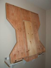 The P&W-RR is designed as a fold-up layout. This provides a spacesaving benefit by allowing you to store the layout in a minimum of space when its not in use. The shelf area is a stable location for trains between operating sessions as the remainder of the layout would be folded up on end when not in use and needs to be cleared of trains before raising it up.
The benchwork is made with 5/8" plywood and a structure of 1"x2" boards. After adding more boards on top to support the scenery backdrop (that will split the layout for two-sided viewing), I will determine if more structure is needed below to maintain a stable working surface. Since a foam base will be used for all of the layout features, the relatively lightweight structure should be adequate for this design. After the layout design is transferred to the table, some of the plywood material will be cut out to reduce the weight and provide access holes to hidden sections of track.
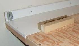 In my implementation, I started with building a shelf that locks onto a support structure attached to the wall. After framing the rest of the layout and adding hinge blocks, the hinges were installed to connect the main table to the shelf. In the photo to the right you can see the white shelf with the left-side locking feature and one of the hinge structures. By unlocking the shelf from the wall, the whole layout can be removed and I intend on making a separate base to allow me to make the layout a standalone design given I want to take it on the road!:o)
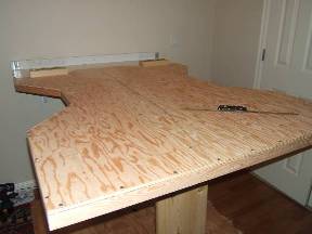 In this view, the layout is lowered for operation with the drop-down leg supporting the table on the end opposite the hinge connections to the shelf. The wider the drop-down leg, the more stable the overall layout will be and I'm thinking that I might add more material to the lower part of the leg to provide it more stability and make it somewhat self aligning. As it is now, I have to use a level to check the table while shifting the leg position as needed to get it right. As an alternative, I might add level indicators under the table to make this more convenient.
Note the Märklin Mikado locomotive and tender that gives you a sense of the overall size of the layout.
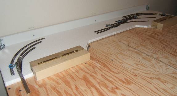 From this photo you can see that the 0" elevation is actually raised up from the shelf surface using 1/2" foam. Some of the track needed for getting started has already arrived and some layout visualization is underway as a means to validate this portion of the layout.
| Return to Start |
|