| Modified distributor with Mopar magnetic pickup |
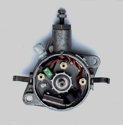 |
| Modified distributor with Mopar magnetic pickup |
|
| Distributor with shaft support installed |
 |
Introduction
I like the 59A style flatheads with their front mounted distributor using the crab style cap, however the choices for converting to electronic ignition are more limited than the later 8BA flatheads. After seeing a mention on line of using Mopar distributor pickups to convert point style distributors I did a search and discovered lots of web articles about converting a variety of distributors to Mopar magnetic pickups and electronic ignition.
However the 59A distributor doesn’t have a lot of room inside and it was questionable whether or not the reluctor and pickup would fit. After some examination of a Mopar distributor in a junkyard it looked possible so I bought one and took it home.
The 59A distributor has a bridge arrangement to support the end of the shaft that fits closely over the cam and needs to be removed to make room for the reluctor . I decided to make a new mounting plate and support plate rather than trying to modify the existing parts. The support plate is fastened to the pickup mounting plate using three 1/4" hex standoffs, tapped for 8-32 screws. The reluctor was bored out in the lathe so it would slip over the cam and was shortened to the same height as the cam. A new mounting plate was cut out of 12 gauge steel and turned on the lathe. When the magnetic pickup was placed on the plate next to the reluctor its pole piece was too high in relation to the reluctor and needed to be mounted lower so the pole piece would be aligned with the reluctor. Otherwise the signal from the pickup would be weaker than normal. After trying a couple of different ways to get it lower, I wound up mounting the pickup upside down. This required making a new angle shaped bracket bent opposite from the original and with the holes for the magnet moved lower. A cutout was also made in the mounting plate to allow the pickup to be positioned as low as possible. Note: make a mark on the magnet so it can be re-assembled in the same orientation; if not, it can reverse the signal polarity if the poles are reversed.
| Front view, new and original pickup mount |
 |
| Rear view, new and original pickup mount |
 |
The sensor mounting plate is made from 12 gauge steel (.105") and the shaft support plate from 14 gauge (.0747"). The parts are cut out oversize and the holes laid out according to the drawings. The two parts are clamped together and the three match drilled 8-32 holes are drilled and tapped through both parts; 8-32 screws are then placed in the holes to keep the parts aligned. A .500" reamed hole is machined in the center of both parts and a mandrel with a close fitting .500" shaft is used to mount the two parts in the lathe after the mandrel is zeroed in on the lathe using a four jaw chuck. The O.D. is then machined per the drawing. The two parts can now be separated and the remaining holes on the mounting plate can be completed after which the plate can be chucked up in the lathe and the center hole enlarged.
The shaft support has a bushing holder that is brazed to it and then bored and reamed to .500". This needs to be done in the lathe so that the hole for the bushing is centered as close as possible in the support plate. It can be dialed in using a four-jaw chuck or soft jaws bored for the plate. The oilite bushing can now be pressed into the holder and the excess trimmed off in the lathe. The 8-32 tapped holes can be drilled for a tight clearance hole for the #8 screws and the excess material can be sawed and filed away per the drawing.
The length of the three spacer posts determine the end play of the distributor shaft, they should be left a little long and trimmed to length after the clearance is determined.
The reluctor was bored out to slip over the distributor cam and held by four small stainless steel non-magnetic set screws, 4-40 by ¼" (?) long. As an added measure I filled the gap between the reluctor and the flats on the cam with some metal filled epoxy. This was done by coating the cam first with paste wax and then coating the inside of the reluctor with the epoxy and pressing the reluctor onto the cam. The tips of the reluctor were aligned with the lobes on the cam. The ideal way to mount the reluctor to the cam would be to grind the cam round and fit it to the reluctor with a light press fit as the Mopar is assembled. Not having the equipment to do this, I settled for the set screw method.
| Reluctor mounted to the cam |
 |
Assembly
The mounting plate can be installed in the distributor with the spacer posts and the shaft support fitted to check for clearance between it and the distributor shaft. The spacer posts will need to be shortened to provide a little clearance to the shaft with the original thrust washers in place. After this is done the pickup can be attached and adjusted for about .006" gap to the tips of the reluctor. Check this at several points around the reluctor to make sure it is running concentric with the shaft.
To set the timing I used the method with a straight edge placed on the wide side of the driven end of the shaft and the shaft rotated clockwise viewed from the rear untill the straight edge is 3/8" past the edge of the upper mounting hole. To make this easier to do I made a round spacer with a shoulder that fits in the mounting hole and the outer diameter that comes out to be 3/8" from the edge of the hole. The end with the shoulder was tapped for a 8-32 screw so it could be fastened to the distributor and a straight edge clamped the tang on the distributor shaft, keeping everything aligned.
The timing point for the reluctor to the distributor is when the tooth of the reluctor is just past the center of the pickup. The wires from the pickup also have to be connected with the right polarity. The ignition coil is triggered on by the HEI module with a positive going signal applied to terminal G of the module and the spark occurs when the module sees a negative going signal at that terminal, which shuts off the coil current. The magnetic pickup will generate a sine wave that goes positive as the reluctor approaches the pickup and then reverses and starts to go negative as the tip of the reluctor nears the center of the pickup. As the reluctor passes the center of the pickup the voltage crosses the zero point, going positive to negative. The ignition will trigger at some small amount of negative going signal which ocurs very close to the center of the pickup. If the wires are reversed or the magnet is placed wrong the signal will be inverted and will go in the negative direction first which will trigger the ignition early; approximately 5/32" from the center of the pickup. I verified this by connecting the high voltage lead from the coil to a spark plug and observed the reluctor with a timing light while cranking the engine. The timing can also be checked if you have a pointer or timing mark on your crankshaft pulley by using the same setup as above, preferably with the plugs out to make it easier to crank the engine.
| Reluctor waveform |
 |
Another method to identify the polarity of the pickup wires is to use an analog voltmeter on its lowest DC range. With the meter positive test lead connected to the positive wire of the pickup, and the negative test lead to the negative wire, rotate the distributor in the correct direction and observe the deflection of the meter needle. If the connections are correct, the needle will go negative as the tip of the reluctor tooth approaches the center of the pickup, and then positive as the tooth passes the center of the reluctor and the pole piece.
When the timing point was determined then the mounting plate was marked for attaching the angle bracket that locks the mounting plate to the distributor housing. The angle bracket was fastened with two 4-40 screws.
Ignition control box
After this project was completed using a Mopar control I changed it out with a GM HEI module. The advantage of this is the HEI module dosen't require a ballast resistor and will drive the low resistance coils like the MSD Blaster. Also it can be connected to your wiring harness with common push on crimp terminals.
|
HEI wiring:
I ran a wire from the "Run" terminal of my fuse panel direct to the + coil terminal and a separate wire from the "Run" terminal to the module. Mount the module on a piece of aluminum sheet approximately 4 x 6 inches to provide a heat sink. Use heatsink compound on the metal mounting surface of the module.
Three of the terminals use 1/4" push on connectors; the "G" terminal uses a 3/16" connector. A ring terminal attached to the mounting hole with the metal tab will provide a solid ground connection. |
 |
Updated on ... February 23, 2011