MiniMill Belt Drive Conversion
After having used my Mini Mill for a few years I managed to overload it while using a
fly cutter and suffered the common occurance of the broken plastic intermediate gear.
An internet search found the cure for this, the Belt Drive Conversion. The quick and
easy way to do it is to buy the kit from the
Little Machine Shop
or Sterling Steele.
but there are drawings available from a couple of websites for those of us that would
rather roll our own.
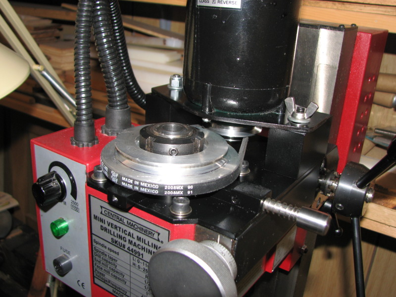
My spindle pulley has a 3.5" OD which is larger than some others use; I had 3.5" diameter
material for the pulley so I used the maximum OD available to take advantage of the
lower speed and hopefully greater torque at the lower speeds. This necessitated a larger
belt and a juggling of the high speed pully sizes to match the larger belt. A Google
search for v belt pulley calculator helped to determine the proper sizes and spacing.
After completing the conversion I measured the maximum RPM on the low range at 1815, and the
high range at 4200 RPM's.

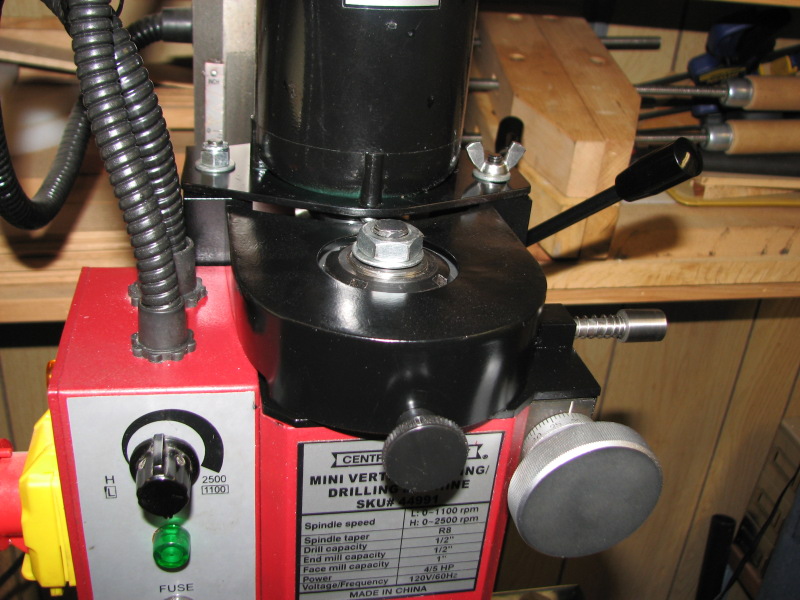
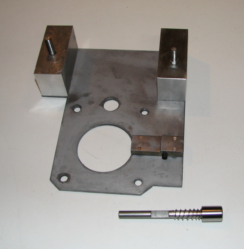
One other difference in my conversion was in the material for the base plate and motor mounting plate;
instead of a rather thick aluminum plate I used 10 guage (.135") steel sheet. The material was
something I had on hand and it allowed me to shorten up the spindle pulley so that the set
screw for the spindle lock nut was accessible.
The belt I used was 1/4" x 14"; Gates 2L0140.
A note on the drawings; the four 1/4" holes on the base plate that attach it to the top
of the mill were hard to dimension as the tapped holes in the mill were not spaced evenly,
so be aware that they may have to be filed out to line up. Also I did not detail the sheet
metal cover or the small block that it attaches to.
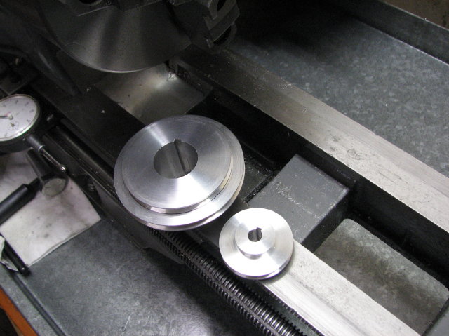
I cut the keyways in the pulleys in the lathe using a boring bar with rectangular bits; by multiple
strokes of the carriage with the spindle locked. The narrow bits cut much easier so by adjusting
the height of the bar to widen the slot seemed to work the best; followed by a cleanup with a
square needle file. I didn't see any need for a set screw on the spindle pulley.
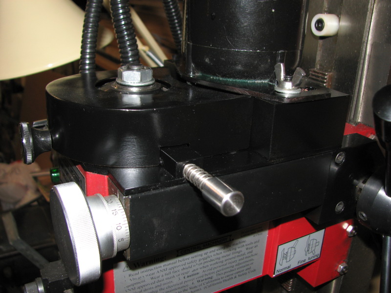
The spindle lock was made with a 3/8 x 5/8 steel bar narrowed to 5/16 to clear the spindle pulley and a 1/4 diameter
piece of drill rod. A set screw mates with a flat on the rod to capture it.
To download the drawing files click on the PDF drawing files link here:
Drawing Files
Back to Index
Created on ... March18, 2009