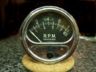
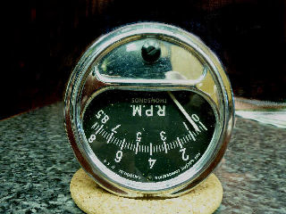
Converting a Sun Tachometer
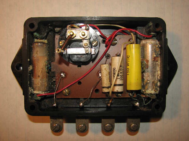
If you find an old Sun Tach with the separate sender box and it has the original batteries in it; it could very well look like this inside; with badly corroded batteries.
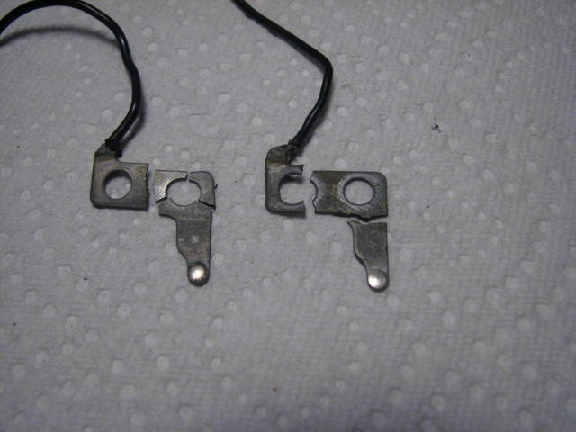
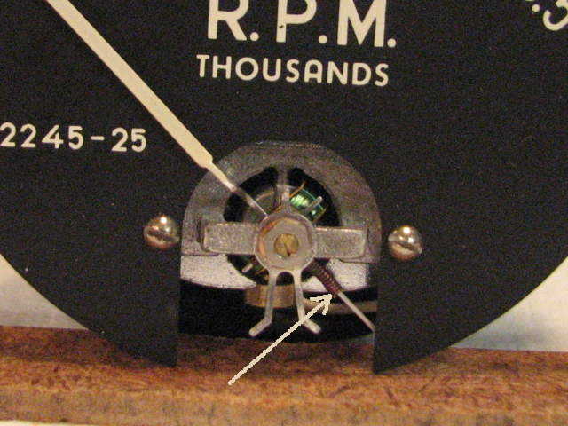
Another problem I found with two different sender boxes were these broken relay contacts. They were the bottom normally open contacts at the bottom of the stack of contacts and I suspect it is metal fatigue from the common moveable contact repeatedly slapping against it.
Also the meter movements in these tachs are unbalanced; if you hold the meter right side up, and then rotate it 180 degrees the needle does not remain near the zero point. I believe this is intentionally done to compensate for the relay operated circuit, making the meter more sensitive at higher RPM's. When you drive the meter with a linear electronic circuit, the meter will read high at upper RPM's. The solution is to re-balance the meter.
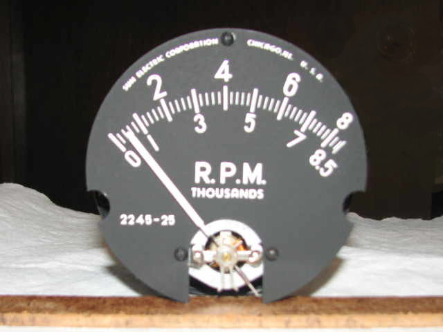
At the bottom of the meter needle there is a coil of wire wrapped around the needle that is a balance weight. Sliding this up and down on the needle changes the balance. It's a trial and error thing to get the balance as close as possible; I found it very difficult if not impossible to get it perfect. There are small cross bars on the needle that also have balance weights but these are very small and I didn't want to risk breaking something so I left them alone. After moving the weight the needle needs to be re-centered. There is a small lever at the back to move the zero center; the adjustment in the front needs to remain in the center position so small adjustments can be made with the centering screw on the outside of the meter case.
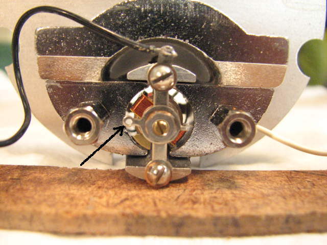
Here the meter is balanced as close as I could get it:
The circuit I ended up using to drive the meter is a "One Shot" multi vibrator using a 555 timer integrated circuit. Each time it is triggered it outputs a 1.1 millisecond pulse. This pulse width is chosen for an eight cylinder engine. A four cylinder would use about a 2 millisecond pulse. And a six cylinder something in between. The meter averages this pulse so it results in a steady reading. There is a variable resistor, or potentiometer that adjusts the meter current to calibrate the meter. the circuit fits on a small experimenters board from Radio Shack.
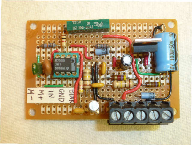
Click the link to open a copy of the schematic for the tach. There are a number of similar circuits on the web using the 555 IC with a variety of input configurations to filter the ignition pulse and trigger the IC. I picked this one from an old Popular Electronics magazine. The transistor gives a good solid trigger signal. Also note that there is no separate connection to +12 volt power; the circuit steals power from the ignition via D1, R1, and C7. When the points are open current will flow to R1 and C7 which filter the ignition pulses to provide a steady DC to the input of the regulator. D1 keeps the charge on C7 when the points close. This saves another input connection so the circuit may be installed in an original transmitter box which has no seperate power connection.
555 Tach SchematicHere are pictures of the tach connected to my homemade tester and meter that is monitoring the frequency applied. Shows the accuracy and linearity over the full range.
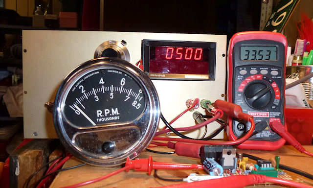
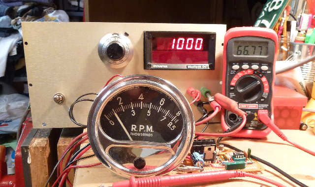
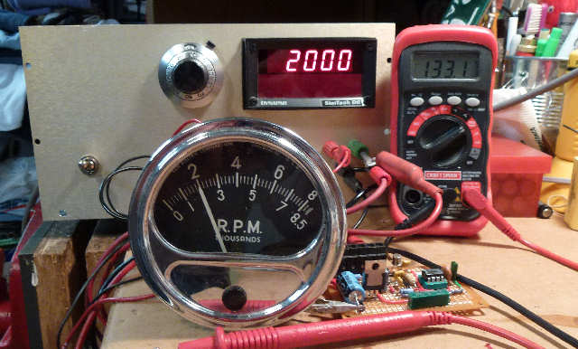
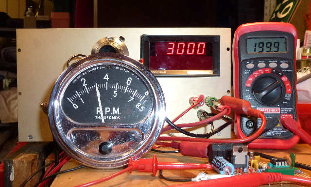
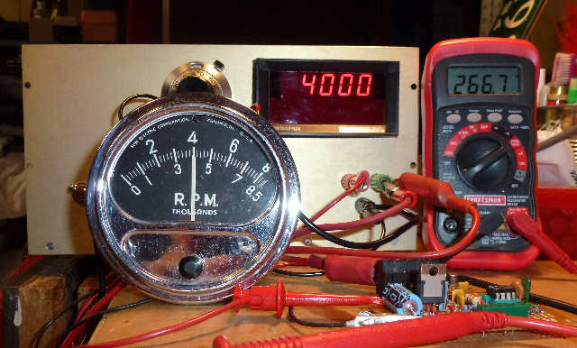
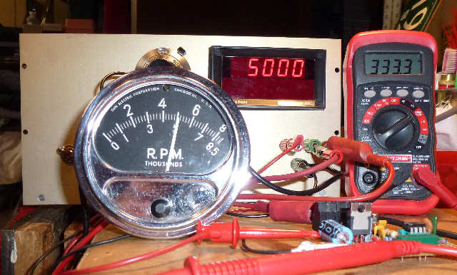
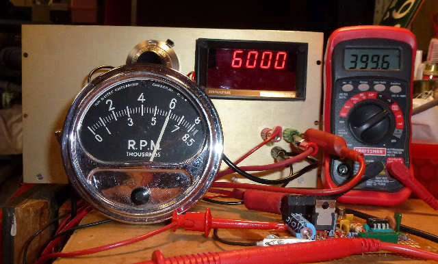
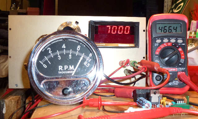
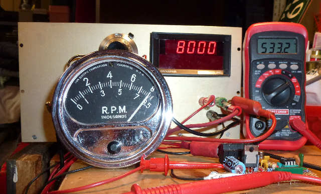
Note these pictures were all taken as I was testing the circuit on the bench with a distributor with coil and spark plug driven by my mini mill and hooked to a battery. I needed the tach filter hooked up to reduce the noise; it may or may not be needed when installed in the car. I will be starting up the car shortly and will report back on how it all works then; so check back for an update.
Well after driving the car I found that I did not need the tach filter. I am using a HEI module instead of points that were used in my test setup so there may be less noise with the Hei ignition.
More pictures of the tach board
Updated on ... July 2, 2016