Crystal radio

Build this Crystal Radio
A crystal radio is a radio that does not require a power source other than the energy contained in the signal being received. With a good antenna, like the random wire you can build by following the instructions on this web site, strong local stations will be very discernable during the day and at night even a few distant "skip" stations may be picked up.
Here's how to make the crystal radio:
First, you must gather the material. Here is a list of what you will need including a possible poor man's source: (If you can't locate a PME source, then try Radio Shack, E-Bay, or Mouser Electronics.)
- A scrap piece of wood about 8 inches square to build the radio on. I used a piece of 1/4" stained panel.
- Sensitive headphones or earphones. The best is the relative high Z (2000 - 4000 ohm) military style headphones. This type is hard to find and may be expensive, so you may use the very inexpensive ceramic earphones instead. Walkman type headphones or earphones will not work. I use two of the ceramic types connected in parallel, one for each ear, for increased volume.
- Variable capacitor (or condenser, which is another name for a capacitor.) You can find this device in an old tube or transistor radios. The air dielectric type is best for this project. That means the plates of the capacitor are separated by an air gap. The small variable capacitors found in pocket-sized transistor radios usually have a plastic dielectric. This type will work OK. Most of the variable capacitors found in radios will be dual section; that is, two capacitors on the same shaft. We will tie these two in parallel for increased capacitance -- shooting for about 450pF (picoFarads.) Find a nice knob that will fit on the shaft of the variable capacitor.
-

1N34 Diode. Detector diode. A 1N34 or 1N60 will work great. You can find them in most transistor radios. They look like a small glass resistor. If you have to buy one, they are cheap -- less than a dollar apiece. -

Fahnstock clip.Terminations. You may use Fahnstock clips (I used these on the antenna and ground connections) or binding posts (I used these to connect the earphones.) Binding posts can be salvaged from an old telephone cell. In a pinch, use small double-nutted machine screws. - Coil form. I used a 1-1/4" x 3-1/2" cardboard tube that was the center spool in a printing calculator paper roll. If you want to use a different diameter form, then use the computer program that you can download and run. It will calulate the number of turns of wire required based on varying coil form diameters and lengths.
- You will need about 50 feet of magnet wire. I used some Litz wire I had. It is 40/44 Litz which means 40 strands of #44 size. This turns out to be about #24 US Standard solid wire size. Litz wire is great for radio frequency coils. You can find Litz wire in CRT monitor or TV picture tube deflection coils. If you can't find a poor man's electronic free source, then this is one of the supplies that a PME guy should buy. You can purchase Litz wire at the Hobby Electronic Parts page. However, if you use solid enameled wire, the radio will work OK. Solid enameled type of wire can be salvaged from old relays, transformers, chokes, and solenoids.

The step by step procedure follows:
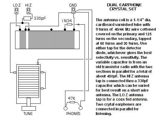
- Wind the coil first. Coat the 1-1/4" x 3-1/2" form with 3 layers of spray polyurathane varnish. Let each coat dry before applying the next one. Punch a pair of holes using a small pin in the side of the coil form about 3/8" from the edge. Feed the #24 solid enamel wire or 40/44 Litz wire through these two holes in such a way as to lock the wire in place. Close wind 9 turns for the primary coil and finish by locking the wire into another pair of holes just like the first pair. Both ends of the wire should be well secured and have 3 inches of lead wire.
- Lock the start of the secondary coil in place as you did before about 3/8" from the end of the primary coil. Close wind a total of 125 turns. At 30 turns and 60 turns, put a twist in the wire that sticks out about a 1/4"; these will be coil taps. Finish off the secondary as you did the primary. You should be about 3/8" from the end of the form when done and again have 3 inches of lead wire on the each end.
- Once again, spray the finished coils with three coats of polyurathane varnish. Put a drop of Elmer's glue on each of the ends of the coils and around the taps to provide additional securing.
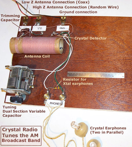
- Mount the completed antenna coil assembly, variable capacitor, and terminals as per the drawing above. You will mount the coil by drilling holes in the board and in the coil form into which to feed some small 6-32 machine screws. (Make sure that when you are drilling holes that you do so on the ends where there is no wire.) I used two small micarta bushings between the coil form and the board so that the bottom of the coil will not touch the board. If you don't have any bushings, you can raise the coil form off of the board by triple nutting the screws. Feed the machine screw up from the bottom of the board, hold the screw into place with a nut on the top side of the board; then place another nut on the screw close to it's top, pass the remaining small piece of screw through the form and nut it again. Do this on both ends of the form. Plastic screws would be great for mounting the coil if you can find them.
- If you use an air variable capacitor, it will have 5 connections. For the first capacitor of the dual section unit, there will be one connection on each side of the stator plates (the ones that do not move.) Please note that these two connections are the same; they are NOT separate. Both are connected to the same set of non-rotating plates. The other section will have two similar connections. The frame of the whole unit is the ground side of both sections. Thus, the rotors are already tied together; the ones that move as you turn the knob. To connect the two capacitors in parallel, simply connect the stator plates together a shown in the wiring diagram. Don't worry if the two sections are different in size, in fact, they probably will be. Also, you may find a variable capacitor with three sections. In that case, connect only two of them together.
- I mounted my air variable by using some small "L" brackets fixed to the board with small wood screws and fixed to the capacitor with very short machine screws. Another way is to put a small length of wire from each of the four stator connection tabs that go down and under wood screws in the board.
- If you use the plastic insulated variable capacitor such as is found in small transistor radio radios, it will be a much smaller unit than the air type and will probably only have three connection tabs. The center tab is the rotor or ground connection, and the outer ones are the stator connections which will be tied together. To mount this type of capacitor, you can epoxy the back side to the board. This means the shaft will point up.
- Mount the knob on the shaft of the variable capacitor. There are several ways that knobs are fitted to shafts. One way is with a small slotted or Allen screw in the side of the knob that is tightened down on the shaft. Another way, used when the shaft is notched into a "D" shape, is to use a knob with a matching "D" shaped hole and a spring clip -- no screw is needed in this case. Another way, common to small transistor type variable caps, is to use a very small machine screw that passes through the center of the knob into a tapped hole in the end of the shaft.
- The terminations for the Lo-Z, Hi-Z, and Ground connections are either Fahnstock clips or machine screws with double nuts. If you use double-nutted screws, then the wires connecting into the circuit will be under the first nut. Make a small loop in the wire(s) then tightened the nut securely down on them. (You may want to add a washer.) Then another nut can be used to make the connection to the antenna lead-in wire and similarly to the ground wire. You may used the same double nutted machine screw scheme for the earphones.
- To make connections to the coil, scrape off the wires to expose the copper after cutting then to length. Tin them with solder. For the taps, scrape and tin them and then solder extension wires cut to the proper length. Start by using the 30 turn tap. Later you can try the 60 turn tap and see if it works better.
- Wire up the circuit as shown in the wiring diagram. This includes wiring in the 330 uuFd (micro-micro farad or picofarad) capacitor, the detector diode, and the 47K resistor. Be careful when soldering the detector diode because too much heat can damage it.
- Finish off the project by putting four stick-on rubber feet on the bottom of the board in each of the corners. In a pinch, epoxy on pencil erasers for the non-slip feet.
-

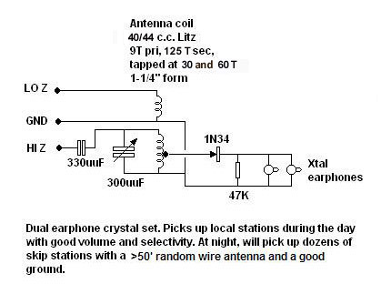
Schematic of the crystal radio
Learn to read schematic diagrams. Eventually you will learn to wire up projects from the schematic without the need of a wiring pictorial.

 Contact me