One Transistor Audio Amp

Build this one transistor audio amplifier
This amplifier will work great with the crystal radio project. It will enable you to pull in weaker and more distant stations. Local strong stations will have extremely loud volume.
List of material:
(If you can't locate a PME source, then try Radio Shack, E-Bay, or Mouser Electronics.)
- A scrap piece about 1 inch square of printed circuit pre-drilled board -- the kind that has little pads of copper around each hole.
- An NPN Silicon transistor. You will have dozens of these if you have salvaged any old electronic devices as described on the main page. Almost any NPN will work; a 2N2222A is what I used. The most important thing is that it is NPN. (If you must use a PNP, then reverse the battery connection.)
- A nine volt battery. A cheapie from the discount store will work fine. You won't need a battery connector since the tiny board will be soldered directly to the battery.
- Small switch. An SPST switch will work fine which means there will be only two connections. If it has more than two, then check it with your ohmmeter and use any two connections that provide simple on/off control.
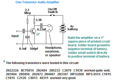
- Three capacitors: 0.1 uF, 0.22 uF, and 500 pF. The values are not critical and may be varied by as much as 50%. The voltage rating of these capacitors should be 10 volts ore more.
- Two resistors: 3.3K and 2.2 meg. You may want to experiment with the 2.2 meg resistor which provides the operating current (bias) for the transistor, particularly if your transistor is something other than a 2N2222A. Try values from 500K to 10 megs. Select the one which gives good clear audio output. The wattage of these resistors are 1/8 watt or more.

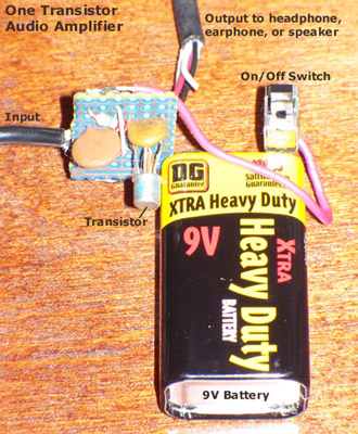
A pictorial drawing of the amplifier.
See if you can wire up this project without the aid of the pictorial. That is, see if you can translate the schematic into a working circuit with a reasonable layout of parts.
- Mount the transistor into three holes in the PC board. Make sure you properly identify the collector, base, and emitter pins (C, B and E pins). Refer to this help file if you need help identifying the pinout of your transistor.
- The edge of the board closest to the emitter pin will be a ground connection. The edge directly opposite on the board will be used for the postive battery connection.
- The edge of the board closest to the transistor's base pin and 90 degrees from the ground edge will be where you want the input to be. The output will be on the edge directly opposite the input. Thus, the four edges of the board will have (1) a gound connection (negative battery connecton), (2) an input connection, (3) a postive battery connection, and (4) an output connection. The input is of course two wires: one to the input connection as described, and one to ground. The output will similarly be two wires, one to the output connection as described and the other also to ground. When tying several wires or components to the same point, use more than one PC board pad soldered together.
- Insert the 0.1 uF input coupling capacitor between the input connection and the base connection of the transistor. You can solder the input connection.
- Insert the 2.2 meg ohm biasing resistor between the base connection and the positive connection. Then insert the 500 pF bypass capacitor between the transistor's base connection and ground. You will have to use an extra pad. Solder the base connections. Be careful and use as little heat as possible so the transistor will not be damaged.
- Connect the 3.3K load resistor between the transistor's collector connection and the positive connection. Connect the 0.22 uF output coupling capacitor between the collector connection and the output connection. Solder them.
- Solder the ground edge directly to the negative terminal (-) of the battery. Please note that this little amplifier pulls so little current that the battery will last a very long time. Mine has been working now for two years -- and the battery was only $1.00 at the discount store.
- Solder one connection of the switch directly to the postive terminal (+) of the battery. Then cut a small piece of red insulated hook-up wire and solder it on the other switch connection. Run the wire to the positive connection on the board and solder.
- I used a small piece of shielded wire with the center conductor soldered to the input connection and the shield soldered to the ground connection; this will be connected to the signal source such as the crystal radio's phone terminals.
- Finish off the project by soldering a ceramic earphone or a magnetic headphone to the output connection and ground. I did not provide a terminal for the earphone or headphone; you may wish to do this.

Schematic of the one transistor audio amplifier
Were you able to wire up this project using only the schematic?

 Contact me