One Transistor Audio Amp
Exploring transistor design:
If you haven't installed the interpreter software yet, go back to the main page and do so. Unzip all the files to a directory of your choice on your hard drive.
Run the FLIP.EXE program (double click on its icon). When the program comes up and gives you the little triangle prompt, enter LOAD QA1AMP and press enter. Follow the instructions on the screen.

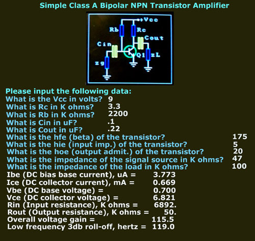
The upper part of the screen shows a schematic of a class A bipolar transistor NPN audio amplifier with simple biasing. What does all that mean?
- NPN transistor means it works with positive voltage on the collector and base, and negative (ground) on the emitter. Electrons in the transistor flow from the emitter to the collector under control of the base current.
- A bipolar transistor is a common silicon or germanium transistor. Another type is the Field Effect Transistor or FET, for which this program is not designed to handle.
- It is Class A because it works as a single LINEAR device. Some power amplifiers work in a non-linear mode.
- The bias scheme is very simple in this project. Only two resistors are used, one for the collector to provide an output voltage and one for the base to establish a small base-to-emitter current for proper Class A operation.
- It is an audio amplifier because it is going to boost the audio frequencies -- the frequencies we can hear. Communication frequencies are defined as 300 to 3000 Hertz. (Hi-Fi is 20 to 20,000 Hertz.)
- What is Vcc in volts? 9
- What is Rc in K ohms? 3.3
- What is Rb in K ohms? 2200
- What is Cin in uF? 0.1
- What is Cout in uF? 0.22
- What is the hfe (beta) of the transistor? 175
- What is the hie (input imp.) of the transistor in K ohms? 5
- What is the hoe (output admit.) of the transistor, uMhos? 20
- What is the impedance of the signal source in K ohms? 47
- What is the impedance of the load in K ohms? 100 (using ceramic earphones, answer "2" for magnetic military style headphones)
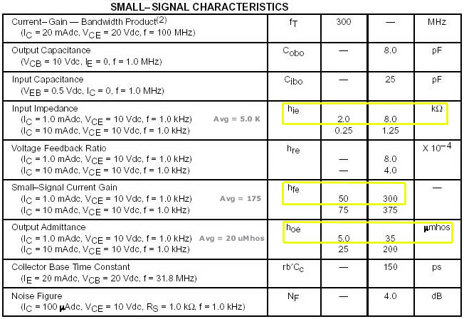
Below is a portion of the spec sheet for the small signal characteristics. Outlined in yellow are the parameters needed for the program. These values have a range because of the variations in manufacturing the device, so I have put the average value next to them. You'll need to do the same for your designs. Of course, you can run the program several times using combinations within the range of parameter values to see how your design will hold up under the wide tolerances that exist in transistors.

small signal characteristics
The program computes the following output using the values in bold above:
Ibe (DC bias base current), uA = 3.773 Ice (DC collector current), mA = 0.660 Vbe (DC base voltage) = 0.700 Vce (DC collector voltage) = 6.821 Rin (Input resistance), K ohms = 1668. Rout (Output resistance), K ohms = 3.10 Overall voltage gain = 115.5 Low frequency 3db roll-off, hertz = 821.3The output is also sent to a file called OUTPUT.ASC in the same directory as the FLIP interpreter. You must open it with WordPad or DOS Edit; it will look funny if opened with Notepad or Microsoft Word.
Run the program with different values of the parameters. (At the triangle prompt, type REPARSE to re-execute it or just type LOAD QA1AMP which will load and run it all over again.) Try designs using other transistors; download their spec sheet from the link above. For instance, try the 2N3904 transistor, another popular transistor for experimenters.
I've added another FLIP program called QCURVES which is in the download package. Run it for an analysis of a Class A amplifier using a 2N3904 NPN transistor with a slightly different approach.

 Contact me