This module implements the 1-wire bus operations for talking to the Maxim DS1825 serial-number/temperature chip. The 1-wire bus is a single-wire bi-directional bus standard originally authored by Dallas Semiconductor. It has a master/slave architecure, capable of handling multiple slave devices. This module implements a bus master for talking to a single slave device. In particular, it detects the device, can read the ROM data (serial number), and can read the scratch-pad memory of the DS1825, including temperature. It implements the ROM commands 0x33 (read ROM data) and 0xcc (skip ROM operation), and the function commands 0x44 (temperature conversion) and 0xbe (read scratch-pad memory). As per the DS1825 data sheet, no data are retrieved by the function data block following the function command 0x44 for temperature conversion: that block is skipped. Similarly, the 'ROM data' block is skipped following the ROM skip command (0xcc).

This module requires a 1-MHz clock and control signals timed for that clock. The done output is pulsed when the operation is finished, including waiting for the temperature conversion to finish.
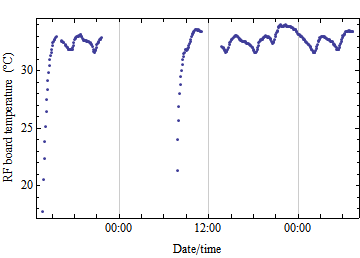
Below is a plot of temperature readings over several hours.

| clk | input | The clock input. |
| reset | input | The reset input. |
| go | input | Pulse to initiate a bus cycle. |
| dq | in/out | The bidirectional 1-wire bus, configured to be pulled high when not driven (the high-impedance state). |
| romcmd | input | The eight-bit ROM command. |
| romdata | output | The 64-bit ROM data consisting of the 8-bit family code, and 48-bit serial number, and 8-bit CRC. |
| funcmd | input | The eight-bit function command. |
| fundata | output | The 72-bit function data consisting of the temperature and other data. |
| busy | output | Indicates that a bus cycle is in progress. At the time it is deasserted, either the done or error port is pulsed. |
| done | output | Indicates that a device was detected and the bus cycle was completed. |
| error | output | Indicates at the end of the reset/presence sequence that a device was not detected on the bus and the bus cycle was aborted. A pulse from the error port flags this event without a corresponding pulse from the done port. |
| output |
There are currently no parameters.
tri1			onewire;	// 1-wire bus
wire			owGo, owBusy, owDone, owError;
wire		[ 7:0]	owFamCode, owCRCr, owConfigreg, owCRCf, owFill8;
wire	signed	[11:0]	owTemperature;  // temperature
wire		[47:0]	owSerNum;	// serial number
wire		[15:0]	owAlarm;	// alarm bits
wire		[ 3:0]	owFill4;	// filler
wire		[23:0]	owFill24;	// filler
owDS1825 owdevice (
    .clk(owClk),		.reset(owReset),
    .dq(onewire),		.go(owGo),
    .romcmd(8'h33),	// read ROM command
    .romdata({owCRCr, owSerNum, owFamCode}),
    .funcmd(8'hbe),	// comvert command
    .fundata({owCRCf, owFill24, owConfigreg, owAlarm, owFill4, owTemperature}),
    .busy(owBusy),		.done(owDone),
    .error(owError)
);