This module is the part of the feedback-loop data path through the controller that provides integral and proportional gain control and an open/closed-loop switch. It takes as input the cavity field and a field setpoint, and outputs a filtered error signal that is later injected into the controller output. Input and output bit widths are parameterized, as are internal bit widths, which are used for coarse scaling of integral and proportional gains and to accommodate the disparity of time constants between NC and SC cavities.

Ports | Parameters | Notes | Example

| clk | input | The sample-clock input. |
| reset | input | A reset input. |
| quad | input | Two-bit vector that provides a quadrant (I, Q, -I, -Q) fiducial. |
| ep05ki | input | Integral gain parameter ki. |
| ep06rot_i | input | rot_i and rot_q together are a gain/phase factor that is applied to the data stream. They provide proportional gain kp and a phase rotation to an I/Q data stream. |
| ep07rot_q | input | See rot_i. |
| fb_in | input | The input data stream from the ADC. |
| setpoint | input | The field-setpoint data stream. |
| dout40 | input | The feedforward signal from the feed forward table. |
| din1_2 | output | Identical to the sig_in signal in jump5.v. |
| fb_out | output | The output data stream. |
| fb_mon | output | The output data stream, before the on/off switch. It is used externaly for loop setup prior to closing the loop. |
| debug_dat | output | A signal multiplexed from a number of internal and external signal. The selector is debug_sel and it destination is the scope. |
| debug_sel | input | A three-bit selector for internal signals destined for the scope module. |
| wd | 16 | The bit width of the set point ports ep05ki, ep06rot_i, ep07rot_q, and setpoint. |
| wIn | 15 | The number of bits in the input port fb_in. |
| wOut | 14 | The number of bits of the output portsfb_mon, fb_out, and debug_dat, and the input port din1_2. |
| sp | 5 | A bit count that serves as a gain scaling factor for the proportional branch. |
| si | 7 | A bit count that serves as a gain scaling factor for the integral branch. |
| apb | 7 | The integrator and proportional/integral summing junction are computed with this number of least-significant bits that are not retained in the output. This is done to preserve precision of the output by not introducing an excess of quantization noise by truncation. |

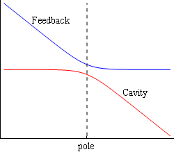
Older versions of this module had a flag distinguishing use with a superconducting (SC) cavity vs normal-conducting (NC) cavity. These technologies have dramatically different intrinsic cavity Qs – ~109 of SC cavities vs ~104 of NC cavities. Although loaded Qs are not so different, this fact still impacts where cavity response functions roll off in modulation frequency (the pole frequency), and hence affects where the frequency response of proportional-integral feedback needs to flatten out. This is why the SC flag needs to affect the relative gains of the proportional and integral feedback paths as this affects the rolloff. So the flag was/is needed to influence the build depending on the application. This is a simplified picture given that other factors, such as cavity detuning and the beam's response, also impact relevant response functions.
The remodeled fb_loop.v module has the SC/NC flag parameterized in the form of bit counts that affect the gains of the proportional (sp) and integral (si) paths in powers of two. Increasing sp and si increase that path's gain by that power of two. More precisely, the corner frequency fc ('pole' in the figure) is related to the integral gain ki by
fc = ki × 2si-10/(2πTs)
or for ki,
ki = 2πfcTs × 210-si
where si is the parameter described above, and Ts is the ADC sample interval. The parameters sp and si should be adjusted to put the host-computer gain settings in a convenient range, i.e., not too small or too large. The former can conceivably introduce quantization noise unnecessarily. As an example, with an SC cavity, one might increase sp and decrease si compared to the defaults. Note that the corner frequency depends only on the integral gain ki and parameter si, and not on the proportional parameters kp and sp. If one intends to change the loop gain while keeping the corner frequency constant, then adjust only the proportional gain kp.
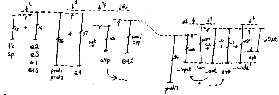
For reference, the following figure is a sketch of the bit alignments within the module.

fb_loop #(.wSP(whost), .wIn(wADC+1), .wOut(wDAC), .sp(6), .si(6)) fb_loop(
	.reset(reset),
	.clk(clk),
	.quad(quad),
	.fb_enable(fb_enable),
	.ep05ki(ep05ki),
	.ep06rot_i(ep06rot_i),
	.ep07rot_q(ep07rot_q),
	.fb_in(fb_in),
	.dout40(dout40),
	.din1_2(din1_2),
	.fb_out(fb_out),
	.debug_dat(debug_dat),
	.debug_sel(debug_sel),
	.setpoint(ramp)
);