|
This group of custom taggers is based on Hasbro's Lazer Tag Team Ops line. The LTTO line has some of the most
up-to-date features of any taggers, right out of the box. While these features can make LTTO gear more difficult to modify,
the end results are worth the time and effort.
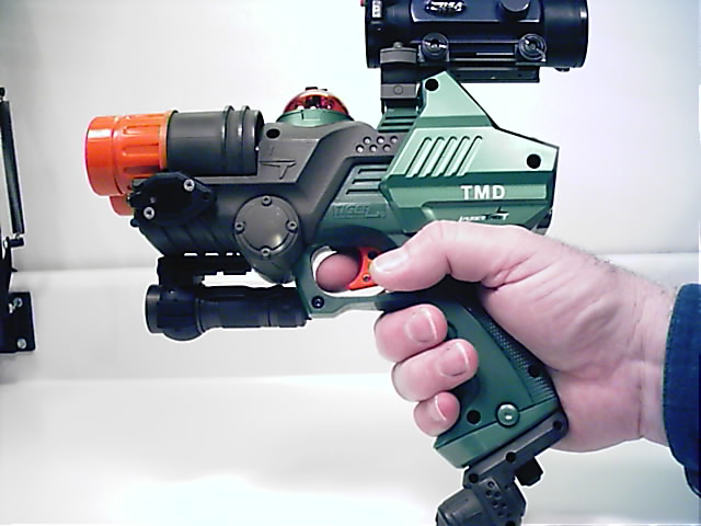
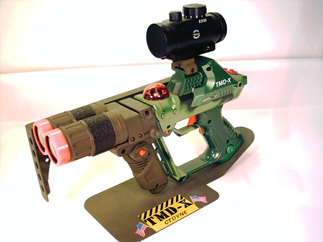
TMD
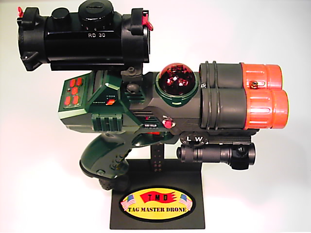
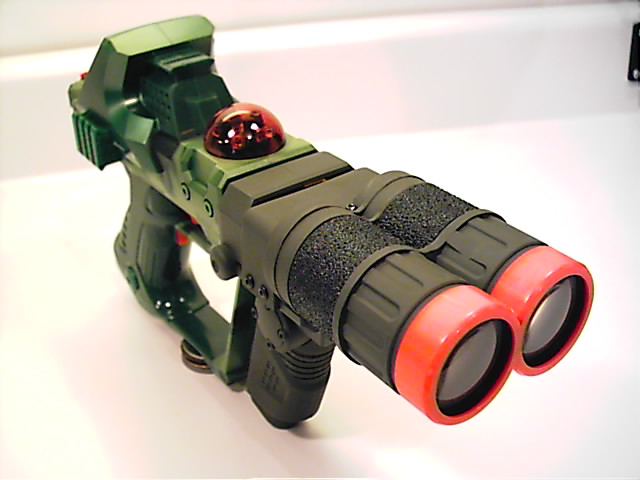
The TMD (Tag Master Drone) is a LTTO IRT-2X (Drone) that has been fitted with a dual lens assembly from a Tag Master
Blaster (TMB). The idea is to retain the compact size of the Drone combined with the excellent range of the TMB. This
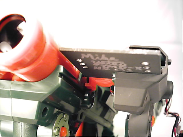
particular unit is TMD #2. It is Mike's personal tagger and has been further modified for use at the forts
and to fit his style. He affectionately calls this one the "Fort Worden Special".
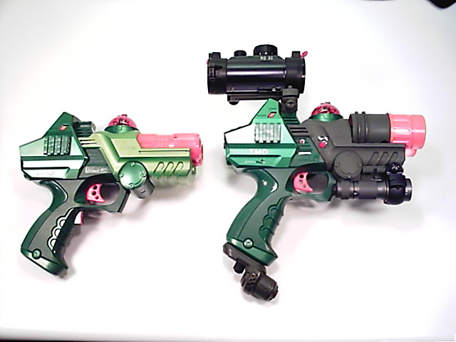
Side by side comparison of an original Drone and TMD #1.
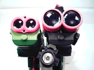
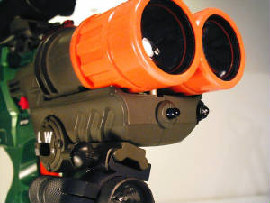
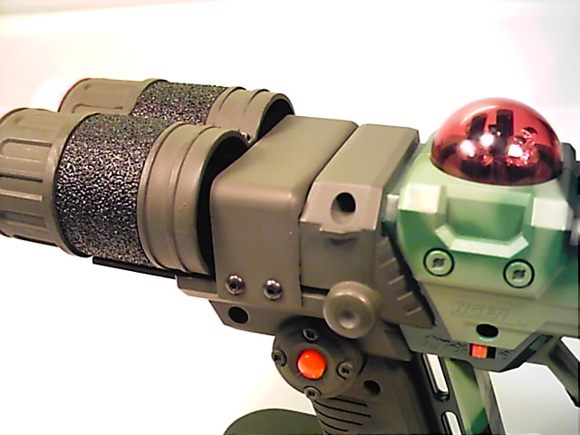
Business end of TMD #1 compared to a Drone. The increased lens diameter of the TMB lens assembly offers a substantial
increase in range. In this image the accesory rail used for lighting, along with the Surefire light, can be seen on the lower
left of the TMD. On the right the red LED tunnel light can be seen. This low power light offers enough illumination to negotiate
the tunnels in Fort Worden with- out giving away your position.
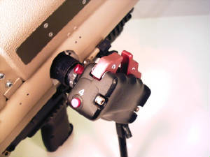
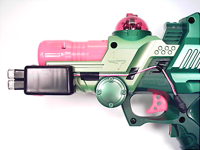
Additional controls fitted to TMD #2 include relocated shield control to reduce accidental shield activation,
silencer control and an IR LED selector switch to go from close-quarters battle mode to long-range mode.
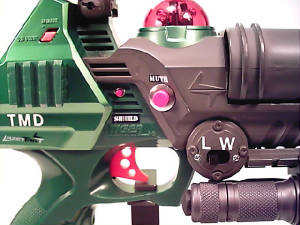
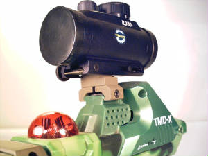
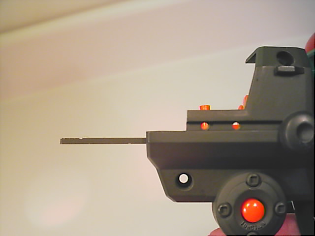
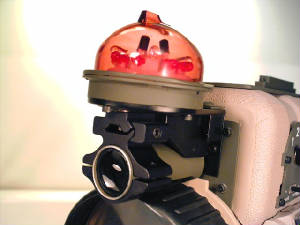
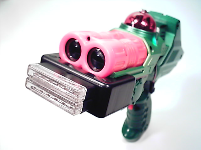
The image of TMD #2 to the right, shows the close-quarter battle mode LED under the main barrels. With no lens, this
LED has a range of only 20-30 feet but a wide spread. Very useful in the tunnels at the forts or for C.Q.B. situations.
This option was added due to the very narrow beam from the TMB lens assembly. The TMB lens works very well at long
ranges. At closer ranges it can be difficult to tag moving targets. The C.Q.B. mode helps make the TMD work well for a wide
variety of tactical situations.
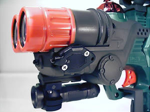
To the left you can see the red LED tunnel light as well as the C.Q.B. mode infrared LED on TMD #2.
TMD #3
TMD #3 was built at the request of Cathie Roman who, along with
her husband David Roman, operate 1Source Laser Tag.
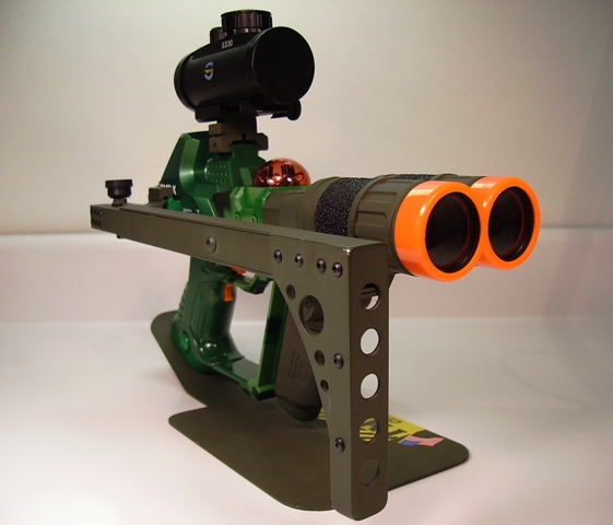
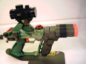
TMD-X
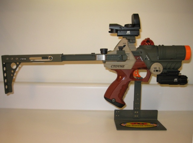
Similar to the TMD in that it uses a dual lens assembly from a TMB, the TMD-X (Tag Master Deluxe) is based on a LTTO
deluxe model. This unit is TMD-X #1 and belongs to Duncan. It has had the shield and reload functions swapped. Now, to reload
you pull the shield trigger and to actvate the shields, the forward grip is squeezed. This was done to minimize accidental
activation of the shields during a game. It is not a big deal if you accidentaly reload, but it can be a problem if you keep
accidentally using up your shields during a contest.
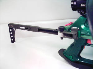
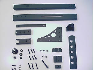
The combination side fold/telescoping stock is all aluminum construction and contains 38 individual parts. It mounts
to the factory accesory rail that comes standard on a deluxe tagger. It can be removed or installed in under a minute. This
stock can be mounted on any LTTO tagger with an accesory rail on the right side.
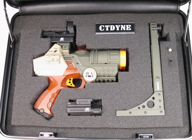
The custom aluminum scope mount is very hardy. The mount takes less than a minute to install and can be used on
any of the upper accesory rails in the LTTO line.

|
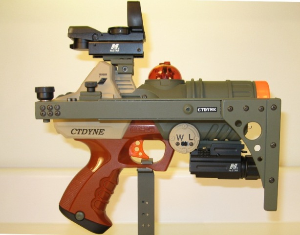
| Duncan tries out TMD-X #1 at Fort Worden, summer 2006. |
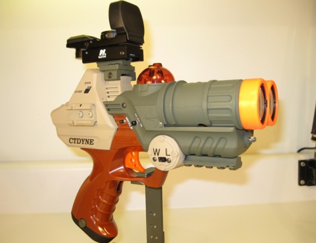
The dual 1.5" TMB lens assembly, custom aluminum side fold/telescoping stock, nifty little aluminum scope mount with
red dot scope, reworked control locations and custom paint, are all very useful and cool modifications, But the real
power of TMD-X #1 is on the inside. Duncan has modified this TMD-X with an auto-fire-upon-lock-on mod. When he points this
tagger at an opponent's tagger, Duncan not only receives a lock-on notification, his tagger automatically fires at the hostile
tagger. But unlike other lock-on mods, Duncan can change the parameters of his taggers response to the hostile tagger. He
actually added a second processor to handle the auto-fire-upon-lock-on duties. He can access this second processor by plugging
a laptop into the modified accessory port on the bottom of the grip. This port is where the thunder pack would normally plug
in. Some of the variables Duncan has tried are: rate of fire, how many rounds to fire at each lock-on, auto reload and
how may magazines to use at each encounter. A very high-tech mod. At times his tagger seems to have a mind of it's own
and will go berserk and keep firing and reloading even when Duncan is not able to see his opponent. It is kind of
unnerving having his tagger going thru ammo faster than you can see the bargraph on his LCD screen keeping count of how many
rounds are left. His next experiment is to write new code for the second processor to compensate for the over-heat
cool down period that follows these wild ammo binges.
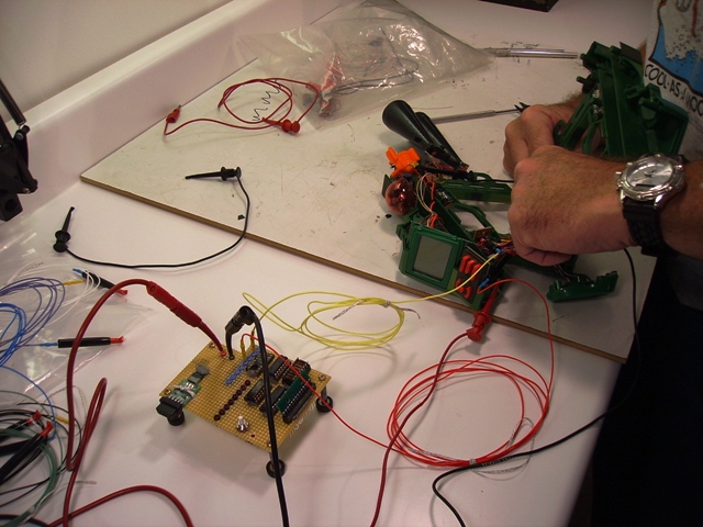
The image above shows TMD-X #1 during the build up. To the left is the custom development board that Duncan
designed and manufactured to facilitate changes to the code for the second processor used for the fire-up-on-lock-on
mod. This board was used extensively during the development of the electronic modifications for TMD-X #1. A laptop used
for writing the revised code was connected to the development board. The TMD-X was also connected to the board. The
effects of the code changes on the TMD-X could then be observed immediately.
TMD-X UPDATE
At the request of those who wish to add the dual lens assembly from a TMB to their own LTTO Deluxe model, CTDYNE offers
this update to detail how it is done. This method is used for the Deluxe. The design for adding a dual TMB lens assembly
to a Drone has been altered as needed to work with the original design of that tagger.
Before you remove the dual lens assembly from your TMB make sure to leave enough of the original wires attached so you
can tell the color of each wire at the aft end of each lens tube.
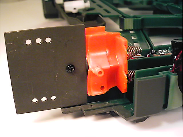
When you open your Deluxe you will see that the aft end of the lower half of the orange lens assembly is also
the forward end of the battery slot. It contains the two springs that the battery tray makes contact with when it is completely
inserted. Rather than fabricate a new set of contacts and a bulkhead to mount them to, we are going to utilize a little
creative saw work and remove enough of this assenbly to still act as the contacts for the battery pack, but eliminate
as much as possible to help keep the over all length of the TMD-X as short as possible. We also need to retain the mounting
hole that goes thru the lower half, as it will be used to mount this modified part to the tagger. It will also serve as one
of the lens assembly mounts.
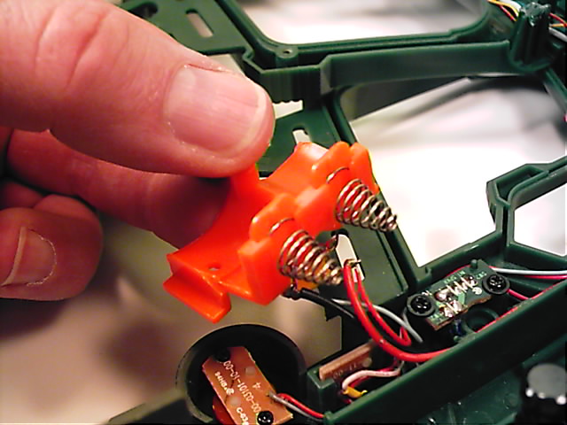
This is what the modified lens tube/battery tray contact should look like when complete. Make sure to leave both of the
small tabs on each side of this part as they help to hold it in position when the tagger is reassembled.
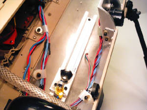
Here is a view of the top of the finished battery contact bulkhead in place. Notice how the length of the part is dictated
by the location of the center mounting hole. In this image you can also see the lens base plate in place. This part should
be mounted as close as possible to the orange battery contact bulkhead to help keep it aligned properly and keep the over
all length of the tagger as short as possible.
The black fastener in the base plate screws into the original lens mount nut. The base plate should be manufactured from
aluminum no thinner than .060. length is 1.85, width is 2.05. The six lens mount holes are tapped to 4-40 thru the base plate
and lens housing. Make sure the lens housing is securly clamped in the proper position so all six holes align properly and
the 4-40 threads are consistant thru both parts. Use care when installing the six mounting screws as these will strip out
easily.
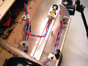
This view shows the right side of the installed battery contact bulkhead. The lens assembly is also shown with the
4-40 button head screws in place.
This image shows an original TMB lens assembly next to a modified lens assembly. A large portion of the finned area
has been removed for use on a TMD-X. Also notice the brass colored screw in the modified lens assembly that replaces the smaller
original black screw. This hole has now been tapped up to 4-40 all the way thru the battery contact buikhead. This hole is
what sets the forward/aft location of the lens assembly.
Also notice how there is an unsightly gap between the aft end of the lens assembly and the forward end of
the body of the tagger. This will be addressed later.
This view shows the battery contact bulkhead, lens base plate and modified lens assembly in place. Notice how all
three parts are carefully fit together with no gaps between them. This is how these three parts should fit together
when all the fasteners are in place. This will help to keep the lens assembly properly aligned should the tagger suffer
a blow from the side.
Also in this view the bottom of the 4-40 screw that goes thru the lens assembly and into the battery contact bulkhead
can be seen. Again, this hole sets the forward/aft location of the lens assembly.
In this view looking aft you can see an original Deluxe on the left and a TMD-X on the right. By comparing the two, you
can see how much must be cut out of the front of the tagger body to allow for the base plate to mount properly.
The base plate must sit flat so the lens assembly is aimed accurately.
This view of the left side of the TMD-X shows how much must be cut out for lens assembly clearance. Also notice
the two holes in the groove. These are drilled and tapped to 4-40 on both sides of the tagger, and are used for mounting the
cover to hide that unsightly gap mentioned earlier.
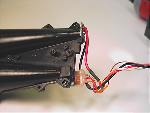
This is all the electrical work necessary to complete the lens swap. To facilitate installation, the lens assembly from
the TMB is turned over when used on a TMD-X. The IR emitter and receiver lens are now on the opposite side as the Deluxe.
Wire hook up is as follows:
Infrared emitter side
red from Deluxe to red to TMB
black from Deluxe to black to TMB
Receiver side
brown from Deluxe to orange from TMB
white from Deluxe to brown from TMB
yellow from Deluxe to red from TMB
Here is the cover that hides the unsightly gap. This is fabricated from the appropriate size project box available at
Radio Shack. Then cut to fit and mount using the four holes shown earlier.
Now that everything is drilled, tapped, cut, fit and checked out it's time to paint and detail your tagger.
Have fun.
SCORPION
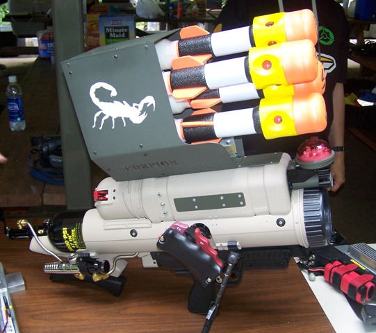
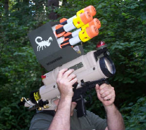
These two images of the Scorpion were taken by Greg at Tagfest NW 2006. Just three days after the ten month build of
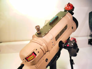
this tagger was completed. This is without a doubt the most complex tagger completed to date at CTDYNE. The Scorpion uses four
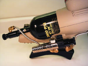
of the same missiles as the LTTO Tag Master Blaster. Instead of pumping by hand to fill an air reservoir for each
launch, the Scorpion has an on-board 3000 psi pneumatic system. Air is stored in an aluminum storage bottle. Primary
and secondary regulator systems supply the final launch pressure to four MAC brand solenoid valves housed in the removable
four round top load magazine.
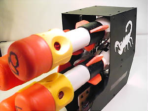
The image to the right shows the four round magazine. It can be removed or installed in less 30 seconds without tools.
Each missile has four infrared LED's that have a "blast" zone of approximately 20' in a 360 degree radius.
On the left is the Scorpion, shown with the magazine removed.Along with the main pneumatic manifold connection, are 30 electrical
connections that pass from the main body of the Scorpion to the magazine.
The image to the right shows the primary and secondary regulator systems. The primary stage regulates the 3000
psi bottle pressure down to 800 psi. The secondary system is adjustable to fine tune the final launch pressure. It is
set to supply approximately 120 psi to each of the four MAC solenoid valves. The launch pressure inside each launch tube drops
to below 40 psi as soon as the valve opens and the missile starts to move down the launch tube. Effective range for each missile
is 40 to 45 feet.
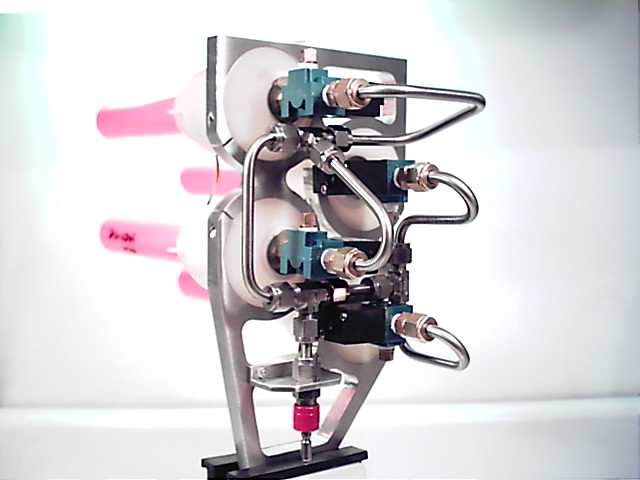
Above is the internal pneumatic system housed inside the magazine. The sheet metal housing bolts to the aluminum
bulkhead and has been removed for this image. The rear of the magazine housing is clear plexiglass to allow the beautiful
craftsmanship of the stainless manifold and valve installation for each launch tube to be viewed from the rear of the
tagger.
The pistol grip has two triggers. The upper is used to activate shields. The lower fires the main IR LED that uses the
4 inch lens at the front of the main body. The fold down grip at the forward end is used when launching the missiles along
with the launch controller on the right side of the Scorpion.
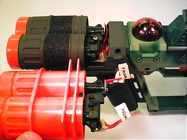
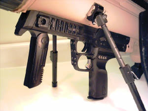
Here the missile launch controller can be seen. This assembly has controls to fire all four missiles independently. With
over 20 electrical connections as well the mechanical conections, it is removeable in less then 5 seconds without tools. With
the launch controller and top load magazine removed the Scorpion becomes a more reasonably sized accurate long range
tagger. The four inch lens along with the TASL-6100 IR LED combine to make an optic package that is capable of outstanding
range.
Here the main body has been opened to reveal the adjustable focal length mechanism. The infrared LED is mounted
onto a carriage assembly that can be positioned anywhere along the rail it is mounted into. This can be done in seconds without
tools. In this image the LED is the aft position.
Here the LED is in the forward position. With the LED positioned aft, the range is quite impressive. Very useful
for long range targets. However the size of the infrared "spot" is very compact making it difficult to tag moving
targets at closer ranges. For environments where close shots are the norm the IR LED can be moved to a more forward position
along the path of the focal length to give a much wider pattern of infrared light. Very useful for fast moving
targets at closer ranges.
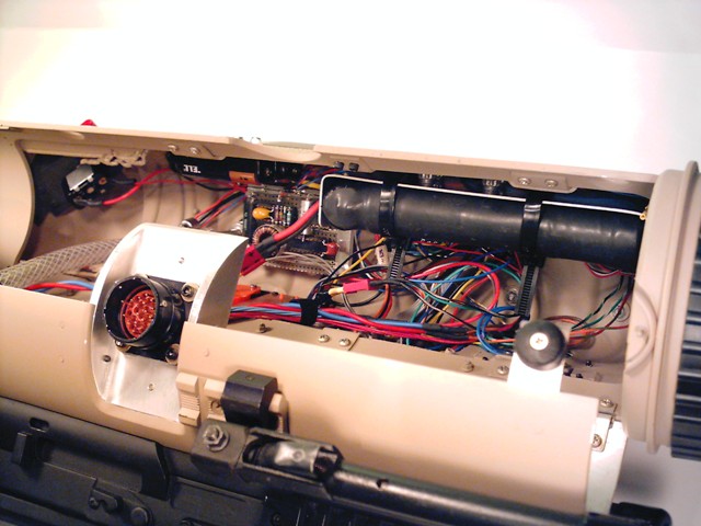
Above, the main body has been opened to the maintenance position. This allows access to the internal pneumatic
and electrical components. To open the main body of the tagger takes less than 5 seconds and can be done without tools. The
launch controller has also been removed for this image. Many of the internal electronic components can be seen along
with rechargable 10.25 volt 2300 mAh NiMH battery pack.
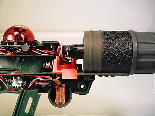
Here is the sensor dome that acts as the target for the Scorpion's opposition. It is mounted with the 1 inch receiver
lens at the forward end of the Scorpion, just above the four inch lens assembly. The receiver lens assembly can pick up signals
from an opponent's tagger which will then be used to give the Scorpion's operator a proximity warning or a lock-on alert
when the Scorpion is pointed in the general direction of a hostile tagger.
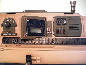
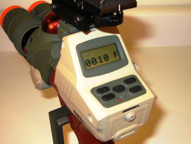
This image shows the controls located on the left side of the Scorpion. Most of these are used to input game parameters
during set up, to alter functions during a game and to keep score during a game. The four postion switch at the left
of the image is used to assign an identification to each missile. The opposing tagger will read this ID when tagged.
At games end, after debriefing each tagger, the players can see who was tagged by who, and how many times. The data is
accessable on the LCD screen in this image.
The Scorpion was a most complex undertaking and could not have been completed without help from others in the tag
community. CTDYNE wishes to thank Duncan, Wayne and Brian for their invaluable help in making Project Scorpion a reality.
SCORPION
UPDATE
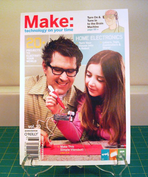
CTDYNE is proud to announce that the Scorpion is now in print. This wild custom tagger is featured
in volume 10 of Make magazine.
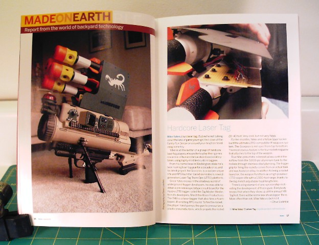
See pages 16-17 for the well written article and photography by Steve Lodefink. What a thrill to
have one of the best custom taggers CTDYNE has been able to complete, featured in the made on earth section of this fine publication.
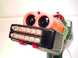
DSM
The DSM (Drone Strobe Module) is an accessory for the LTTO Drone (IRT-2X) model. The DSM housing has two tabs that slide
tightly into the two grooves Hasbro was good enough to mold just below the dual barrel assemblies on both sides
of the tagger. Once the unit is pressed completely into the grooves, one small piece of tape on the bottom is all that is required
to secure the DSM to the Drone.
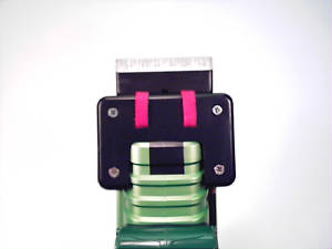
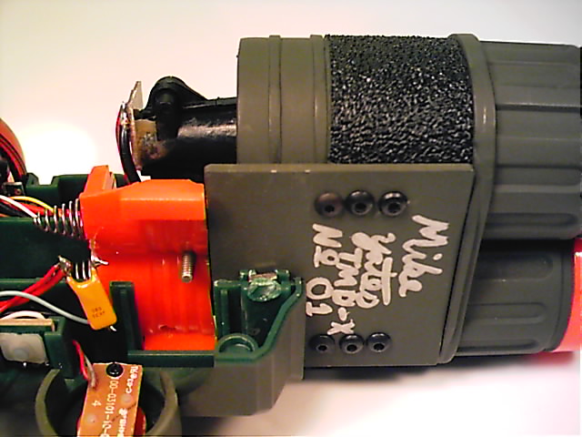
|
| Bottom view of a DSM shown mounted on a Drone |
The switch used to activate the strobe function is mounted with a small piece of double back tape to hold it
where the users thumb can squeeze it. Three small pieces of tape secure the wires out of harms way. With a little practice
it can be activated at the same time the trigger is pulled.
The DSM is a completely self contained unit. It is powered by a very small onboard 12 volt battery. The unit is very
light weight and can be installed and removed in minutes. One of the nice features of the DSM is that it requires no modification
to the tagger to be used.
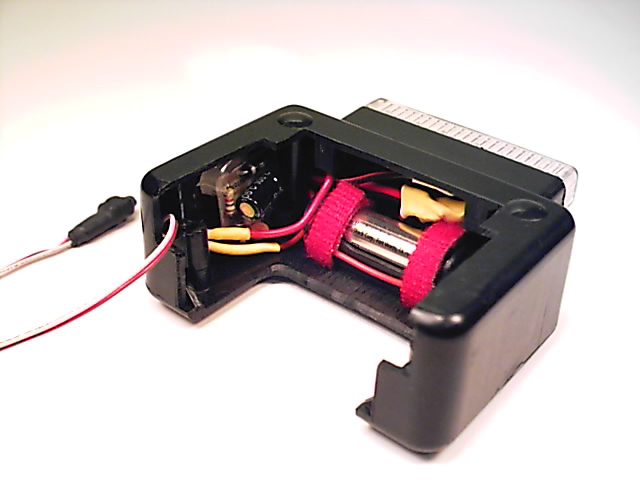
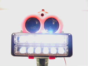
There are twelve bright LED's behind the clear covers. In the image below/left, the covers have been removed. The
covers have a type of lens molded into the front. It helps to focus the white light from the LED's. When viewed from the front
in low light conditions the DSM emits a very bright flash.
|