| Miscellaneous items |
The feedback data path in the controller shown in the figure is through the modules DDR_IQ.v performing I/Q detection, fb_loop.v providing proportional and integral gain, jump5.v where a feed-forward (FF) signal in injected, Limiter.v that limits the rf output to a pre-defined level, and UpConv.v, which performs Larry Doolittle's 10-to-50 MHz (IF2 → IF1) upconversion. These modules are described below. The RFInhibit function is implemented in a code block at the top level.
Descriptions of the Verilog modules can be reached through this list. The block diagram below, shown for a powered system with feedback, contains a number of clickable regions pointing to some of these documents and others.
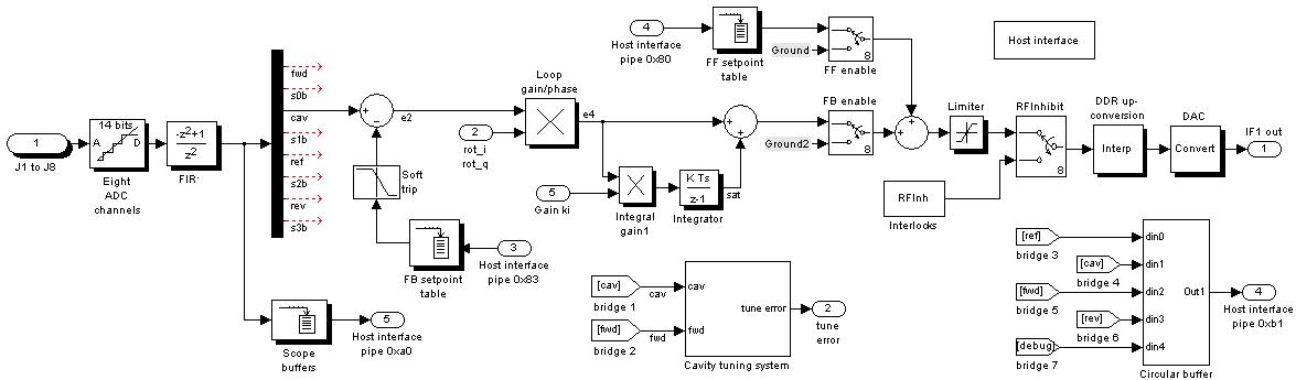
More peripheral functions are the feed forward and feedback setpoint tables consisting of 1024 I and Q samples. The former allows the control of rf power with feedback off, and in systems containing no feedback. Its output may be triggered either on demand or repetitively. One-shot triggers may be through an external source or by software command. The latter (fb-setpoint) table sets the level of the cavity field when the feedback loop is closed. It may be triggered non-repetitively externally and via software. It is different from the feed forward table in that its output is linearly interpolated. It is used in the booster exclusively. (In other systems, an I/Q pair provides the set point. Programming this table is described in more detail here. Both tables may be output with a wide range of durations, from 25 μs (51 μs in the case of the ff table) to 26 s.
The FIR block is a low-order notch filter that removes the z = ±1 content of the eight data streams. The narrow-band signal of interest resides around z = ±j, leaving what is interpreted as an interleaved I, Q, -I, -Q ... vector component pattern (IF2 frequency) without baseband offsets.
The adder computing e2 and the proportional and integral gain blocks are housed in the module fb_loop.v. Coarse proportional and integral gains within this module are configurable at build time, which is used to ensure that the gains kp and ki provided to the module by the control system are not too small or too large for the cavity technology (NC vs SC) in use.
An rf signal is supplied, with or without feedback, to the output data stream via the feed-forward table. This table can be programmed with arbitrary waveforms of 1024 points. In non-linac builds, points in this table are regarded as I/Q pairs, and output of these pairs by the table can be stretched in time, where the data stream is padded with I, Q, -I, -Q ... pattern of the current I/Q pair. Linac builds are configured with the module TableFast, which is not zoomable in this sense, but instead outputs its contents at the full DAC (2×fs) rate. Data written to this version must pre-upconverted to the IF1 frequency.
The output of the feed-forward table (non-linac builds) is combined with the feedback signal (when present) in the module jump5, fed to the limiter, RFInhibit interlock block, up-conversion logic (IF2 → IF1), and finally the DAC. The limiter clips the intensity of the output data stream while preserving phase. The level at which it limits is set at build time. Its implementation is via a serial Cordic with about 0.4-μs latency at a 40-MHz sample frequency. There is further information about upconversion in the documentation of the module, and in one of L. Doolittle's pages.
As was mentioned, the scope span and feed-forward table duration are zoomable (except the latter in linac builds). How the zoom control affects these two modules is described here.
When the build targets CESR-cavity systems for the storage ring, the optional soft-trip block provides a controlled ramp down of the feedback setpoint for response to certain less-critical trips. It more gently shuts off the rf in response to such trips. It does this to avoid the greater disruption caused by a harder trip by the RFInhibit module at full rf power when a fast trip is not required. Following ramp down, the soft-trip module delivers a trip to the RFInhibit module, which blocks rf output by the controller. The duration of the ramp down is in the millisecond range. The idea of the soft trip comes from CLS.
The loop gain/phase block of the diagram, housed in fb_loop.v, adjusts the loop's gain and phase via a complex-arithmetic calculation. I and Q gain components, containing both gain and phase information, are provided to the module by the host system. The phase part is there to set the total loop response to negative feedback, and the gain part sets the loop gain. A discussion about how to set loop phase for negative is given here.
A scope function records 1024 samples in each of eight signals. They are uploaded and displayed through the host interface. The recorded channels include cavity field, the forward signal, the reverse signal, reference, and others. One other, the debug signal is itself one of eight signals multiplexed within the feedback amplifier module, fb_loop.v. Like the setpoint tables, the scope's sampling rate may be varied over six orders of magnitude. The Fourier transform of the eight signals may be displayed through the Matlab program. Several sources within the controller are wired to trigger acquision.
The circular-buffer block is a much larger memory block (32 Mbyte) used to capture data from five data streams. This memory block is configured to continuously acquire data from these five channels, wrapping at the end of the memory – this to provide high-resolution data both before and after critical events.
A number of interlock blocks are instantiated, along with a number of external trigger inputs. One, in the storage ring, trips the soft-trip module; in the booster where the soft trip is not present, the same input instead triggers the feedback ramp table for booster ramps; in the linac the signal will probably pulse the rf through the FF table.
The diagnostic control panel is shown below. Under the Scope section, the button marked stopped toggles triggering of the scope between off (shown) and free running. The scope is also triggered by a variety of internal and external events, such as trigger of the FF table, various trips, external trigger input, and the single-shot button. The time-span selector applies to both the scope and FF table. The pause selector determines the interval between data downloads and display, even though acquisition may occur more frequently depending on the time-span selector. In any case, data upload only occurs when acquisition completes and a trigger out is detected by polling. The single-shot button flashes green during data downloads.

Clicking on the plot inserts a vertical cursor line. The time of the line is displayed, as well as the values of the traces at the cursor time. The cursor is removed by clicking elsewhere in the window.
Under the Scope section, the button marked stopped toggles triggering of the scope between off (shown) and free running. The scope is also triggered by a variety of internal and external events, such as trigger of the FF table, various trips, external trigger input, and the single-shot button. The time-span selector applies to both the scope and FF table. The pause selector determines the interval between data downloads and display, even though acquisition may occur more frequently depending on the time-span selector. In any case, data upload only occurs when acquisition completes and a trigger out is detected by polling. The single-shot button flashes green during data downloads.
The FF single-shot and stopped/running buttons are grayed out when the enable checkbox is not checked. FF table triggering functions similarly to scope triggering. When not free running, it can be triggered by the single-shot button, from software, and an external source when so configured, e.g., when the target system is the linac. As was mentioned, when free running, the scope is triggered by the FF. Because of this, the scope triggering should not also be free running when FF is free running.
A few things that often trip us up while we are trouble shooting: the first that the FF setpoint slider on the second panel (below) must be nonzero for there to be an effect; second that when a FF waveform is selected that is zero on the ends, the FF will inject nonzero signal only when the FF table is being output, and not when only the scope is free running; third that the behavior of the controls is quite different while feedback is on compared to off due to saturation, latching, etc.; and lastly when using feedback, be sure that gains are nonzero. Checking these things often solve problems.
The FB ramp button triggers the FB-setpoint ramp table. As was mentioned earlier, this table is used to provide a fixed setpoint, ramp between setpoints, and perform controlled ramps such as for the booster ramp cycle. The sliders and edit boxes on the second control panel (below) are adequate for the first function, but the second and third require more involved set up, which cannot easily be managed through a graphical user interface. Thus programming is required, which is described in a separate page. For this reason the FB ramp trigger button is of little practical use, at least for now, although it does trigger the ramp.
The scope delay setting is in I/Q samples ranging from 0 to 2047, where an I/Q sample consists of an I, Q pair. There are 512 of them in each scope channel, so the delay can be up to four spans of the scope. The FF and FB tables similarly hold 512 I/Q pairs. In FF single-shot mode, the FF table outputs its 512 samples, then returns to its first I/Q pair and outputs that pair repetitively in the I, Q, −I, −Q ... (IF2) pattern. So when the FF table is not free running, it can be outputting zero samples even if there are non-zero samples in the interior of the table, such as with the long-pulse waveform. The short-pulse waveform is zero after about 130 samples out of the 2047.
Also be aware that the feed-forward-table output span differs from the scope span because of the latter's 4n+1 quadrant sampling interval. The difference is most evident at short spans. At long spans the two are indistinguishable.
The second panel of the Matlab graphical user interface is shown below. Click the on it to enlarge/shrink.

Provision for interlocks is shown under the trips button group. Each of the buttons has a latch, a trip/reset button, and trigger/trip sources. AVAGO2 refers to an external trigger input, which, when the target system is the storage ring, triggers the soft trip module. Any trigger interpreted as a trip triggers the RFInhibit trip (in powered systems), including the soft trip module. Trips in turn trigger the scope and circular buffer. All of these latches have triggers to/from, and status indicators to, the host interface.
Lastly, under control of the Matlab user interface, the scope data are uploaded when the "take a snapshot" button is clicked. Plots are generated for both the time domain and frequency domain for all among the eight channels that are nonzero.
A number of rf signals are sampled as I/Q pairs and returned via dedicated Opal Kelly wire-out end points. These signals and end-point assignments are listed in the spread sheet in the worksheet 'wire outs'. When the feed-forward table output mode is not free running, the I/Q pairs are acquired continuously, with acquisition synchronized only to a reference rf quadrant.
If the feed-forward table is output in the free-running mode, however, then the timing of acquisition is controlled by the feed-forward table, in particular so the data are acquired at a fixed fraction of the table following the start of output of the table. The delay is set by a parameter of the ffSetpointTable module. Note that if the table output duration is long, then the end points are updated at correspondingly long intervals.
Many connections to and from the host interface are signed integers — not just the I/Q snapshots, but also set points, gains, etc. By convention, the most-significant bits of these numbers are aligned with the most-significant bit of host-interface port, regardless of the number of bits. The advantage is that one does not need to know the number of bits of the parameter to interpret the set point or readback. This choice also helps make the host-software and logic agile with respect to bit widths, such as ADC, DAC, gain parameter, etc.